Table
3-2
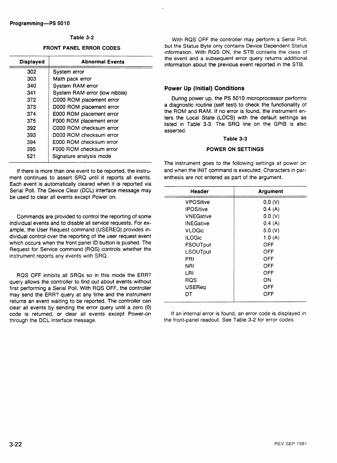
FRONT PANEL ERROR CODES
If there is more than one event to be reported, the instru-
ment continues to assert SRQ until it reports all events.
Each event is automatically cleared when it is reported via
Serial Poll. The Device Clear (DCL) interface message may
be used to clear all events except Power on.
Displayed
302
303
340
341
372
373
374
375
392
393
394
395
52 1
Commands are provided to control the reporting of some
individual events and to disable all service requests. For ex-
ample, the User Request command (USEREQ) provides in-
dividual control over the reporting of the user request event
which occurs when the front panel
ID button is pushed. The
Request for Service command (RQS) controls whether the
instrument reports any events with
SRQ.
Abnormal Events
System error
Math pack error
System RAM error
System RAM error (low nibble)
COO0 ROM placement error
DO00 ROM placement error
EOOO ROM placement error
FOOO ROM placement error
COO0 ROM checksum error
DO00 ROM checksum error
EOOO ROM checksum error
FOOO ROM checksum error
Signature analysis mode
RQS OFF inhibits all SRQs so in this mode the ERR?
query allows the controller to find out about events without
first performing
a
Serial Poll. With RQS OFF, the controller
may send the ERR? query at any time and the instrument
returns an event waiting to be reported. The controller can
clear all events by sending the error query until a zero (0)
code is returned, or clear all events except Power-on
through the DCL interface message.
With RQS OFF the controller may perform a Serial Poll,
but the Status Byte only contains Device Dependent Status
information. With RQS
ON,
the STB contains the class
of
the event and a subsequent error query returns additional
information about the previous event reported in the STB.
Power Up (Initial) Conditions
During power up, the PS 5010 microprocessor performs
a diagnostic routine (self test) to check the functionality of
the ROM and RAM. If no error is found, the instrument en-
ters the Local State (LOCS) with the default settings as
listed in Table 3-3. The SRQ line on the GPlB is also
asserted.
Table
3-3
POWER ON SETTINGS
The instrument goes to the following settings at power on
and when the INlT command is executed. Characters in par-
enthesis are not entered as part of the argument.
Header
I
Argument
-
-
VPQSitive
IPOSitive
VNEGative
INEGative
VLOGic
l
LOGic
FSOUTput
LSOUTput
PRI
N R I
LR
I
RQS
USEReq
DT
0.0 (V)
0.4 (A)
0.0 (V)
0.4 (A)
5.0
(V)
1
.o
(A)
OFF
OFF
OFF
OFF
OFF
ON
OFF
OFF
If an internal error is found, an error code is displayed in
the front-panel readout. See Table
3-2
for error codes.
REV
SEP
1981