ticular board, pull the board toward the rear of the
Multipin Connectors
The pin connectors used to con,nect the wires to the
interconnecting pins are clamped to the ends of the wires.
To replace damaged multipin connectors, remove the old
pin connector from the holder. Do this by inserting a scribe
between the connector and the holder and prying the con-
nector from the holder. Clamp the replacement connector to
the wire, Reinstall the connector in the holder.
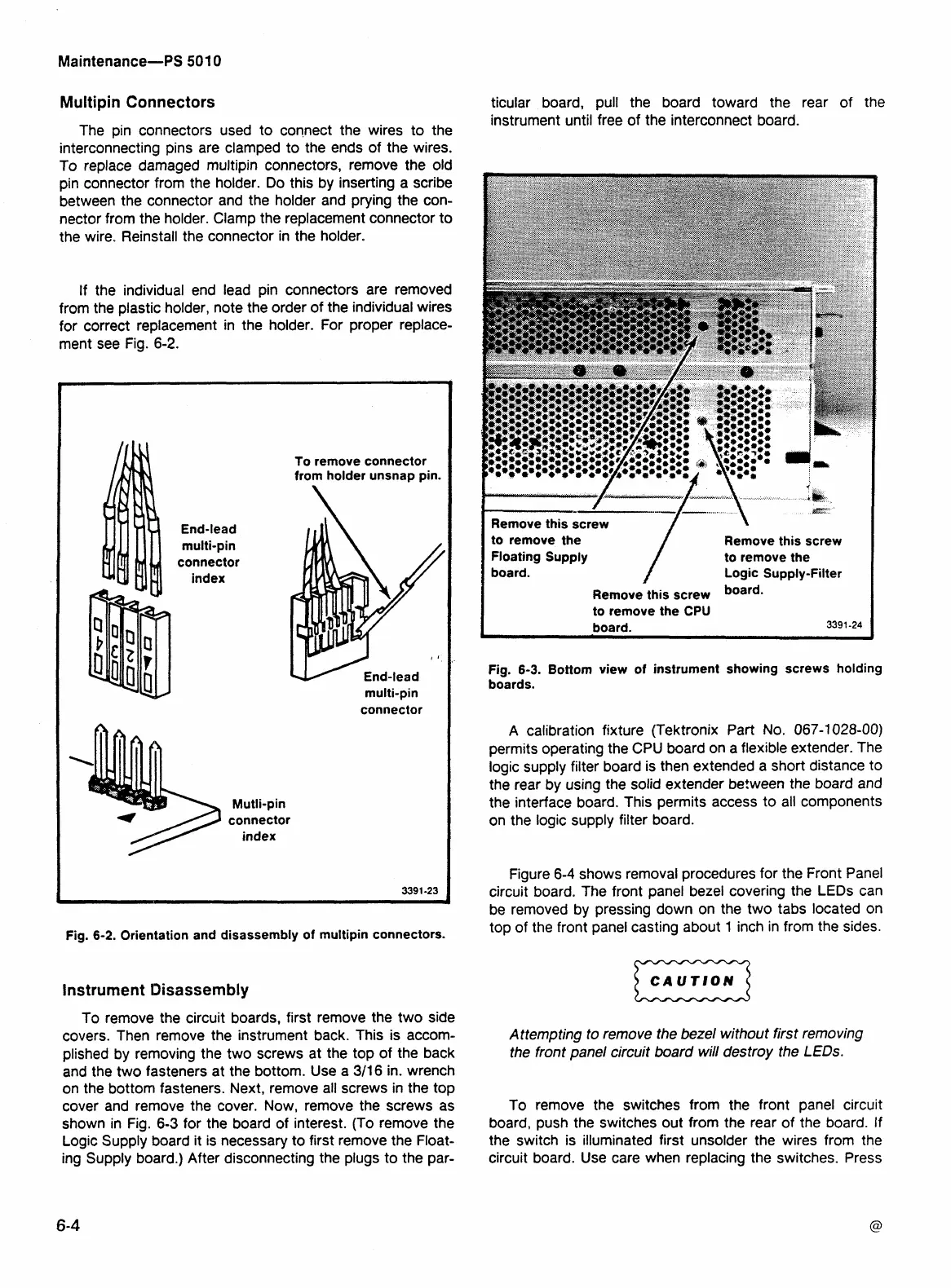
If the individual end lead pin connectors are removed
from the plastic holder, note the order of the individual wires
for correct replacement in the holder. For proper replace-
ment see
~i~.-6-2.
End-lead
multi-pin
connector
index
Mutli-pin
connector
index
To remove connector
from holder unsnap pin.
multi-pin
connector
Fig.
6-2. Orientation and disassembly of multipin connectors.
Instrument Disassembly
To remove the circuit boards, first remove the two side
covers. Then remove the instrument back. This is accom-
plished by removing the two screws at the top of the back
and the two fasteners at the bottom. Use a
311 6 in. wrench
on the bottom fasteners. Next, remove all screws in the top
cover and remove the cover. Now, remove the screws as
shown in Fig.
6-3
for the board of interest. (To remove the
Logic Supply board it is necessary to first remove the Float-
ing Supply board.) After disconnecting the plugs to the par-
instrument until free of the interconnect board.
*&
sz'
Remove this screw
to remove the
Remove this screw
Floating Supply
to remove the
board. Logic Supply-Filter
Remove this screw
board-
to remove the
CPU
board. 3391 -24
Fig. 6-3. Bottom view of instrument showing screws holding
boards.
A calibration fixture (Tektronix Part
No.
067-1028-00)
permits operating the CPU board on a flexible extender. The
logic supply filter board is then extended a short distance to
the rear by using the solid extender between the board and
the interface board. This permits access to all components
on the logic supply filter board.
Figure
6-4
shows removal procedures for the Front Panel
circuit board. The front panel bezel covering the LEDs can
be removed by pressing down on the two tabs located on
top of the front panel casting about 1 inch in from the sides.
Attempting to remove the bezel without first removing
the front panel circuit board will destroy the
L
EDs.
To remove the switches from the front panel circuit
board, push the switches out from the rear of the board. If
the switch is illuminated first unsolder the wires from the
circuit board. Use care when replacing the switches. Press