Calibration-PS
SO
10
Internal Adjustment Procedure
e.
Remove
all
front panel connections for the next step.
10.
Adjust
-1
0
a. Make certain the PS
5010
is in the high power mode.
NOTE
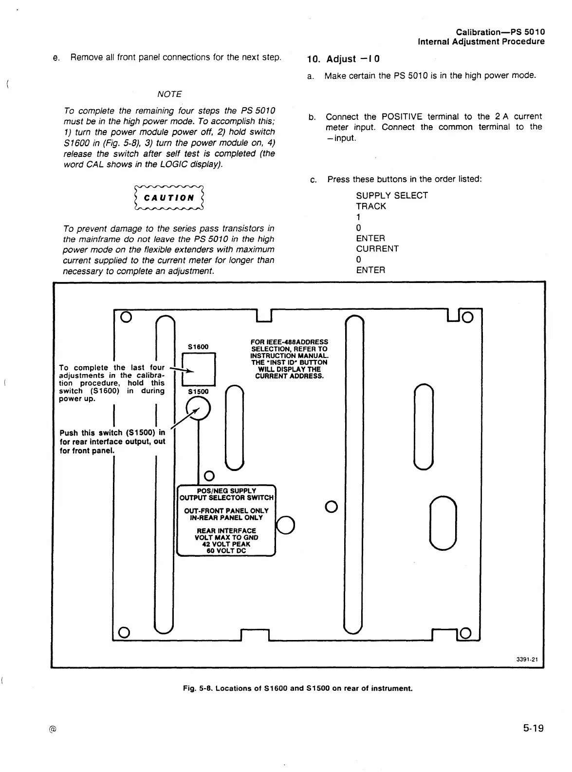
To complete the remaining four steps the
PS
5010
must be in the high power mode. To accomplish this;
b. Connect the POSITIVE terminal to the
2
A current
I)
turn the power module power
off,
2)
hold switch
meter input. Connect the common terminal to the
S
1600
in (Fig.
5-8),
3)
turn the power module on,
4)
-input.
release the switch after self test is completed (the
word
CAL
shows in the
LOGE
display).
c.
Press these buttons in the order listed:
CAUTION
D
SUPPLY SELECT
TRACK
FOR IEEE-488ADDRESS
SELECTION, REFER TO
INSTRUCTION MANUAL.
THE "INST ID" BUITON
WILL DISPLAY THE
CURRENTADDRESS.
OUTPUT SELECTOR SWITCH
OUT-FRONT PANEL ONLY
IN-REAR PANEL ONLY
REAR INTERFACE
I
VOLT MAX TO GND
42
VOLT PEAK
60
VOLT DC
Fig.
5-8.
Locations of
S1600
and
S1500
on rear of instrument.