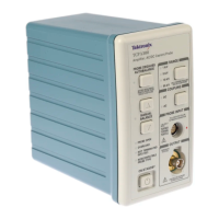
TCPA300 and TCPA400 Performance Verification
3. Make or verify t
he equipment settings as shown:
Table 4: Equipment settings
Digital mu ltimeter
Measurement Type
DC volts
Range Autoranging
Current source
Voltage 6 V
Current
100 mA
Output Off
TCPA300 and TCPA400 amplifier
Coupling DC
Proced
ure
After the equipment is set up, proceed as follows:
4. Connect the Calibration Adapter to the PROBE INPUT of the amplifier.
5. Perform the following steps for each of the Range settings: (See Table 5.)
a. If you
are checking a TCPA300, set the amplifier to the desired Range
setting. (See Table 5.)
b. Enab
le the output of the current source.
c. Record the exact measurement of the digital multimeter as M
1
.
Tab
le 5: DC gain accuracy test for the TCPA300 and TCPA400
Am
plifier
Ra
nge, A/V
Current
source
ou
tput
Expected
output, V
E
(V
DC)
Measured
output, M
1
(V
DC)
%Error,
ca
lculated
1 100 mA 5.0000
5
100 mA 2.5000
1
0
1
00 mA
1
.2375
50 100 mA 0.4835
T
CPA300
50 (COMP)
1
100 mA 0.4585
TCPA400 1 A/mV
100 mA 2.5000
1
Both 10 A/V and 50 A/V RANGE LEDs light.
d. Calculate the %Error between the measured output, M
1
, and the expected
output (V
E
) %Error as follows:
TCPA300/400 Amplifiers and TCP300/400 Series Current Probes Service Manual 7

 Loading...