TCPA300 and TCPA400 Performance Verification
AC Coupling
The following test checks that the AC coupling circuit of the amplifier functions
properly. First, you measure a square-wave signal in DC coupling mode and record
the value, a n
d then switch to AC coupling and measure the signal amplitude.
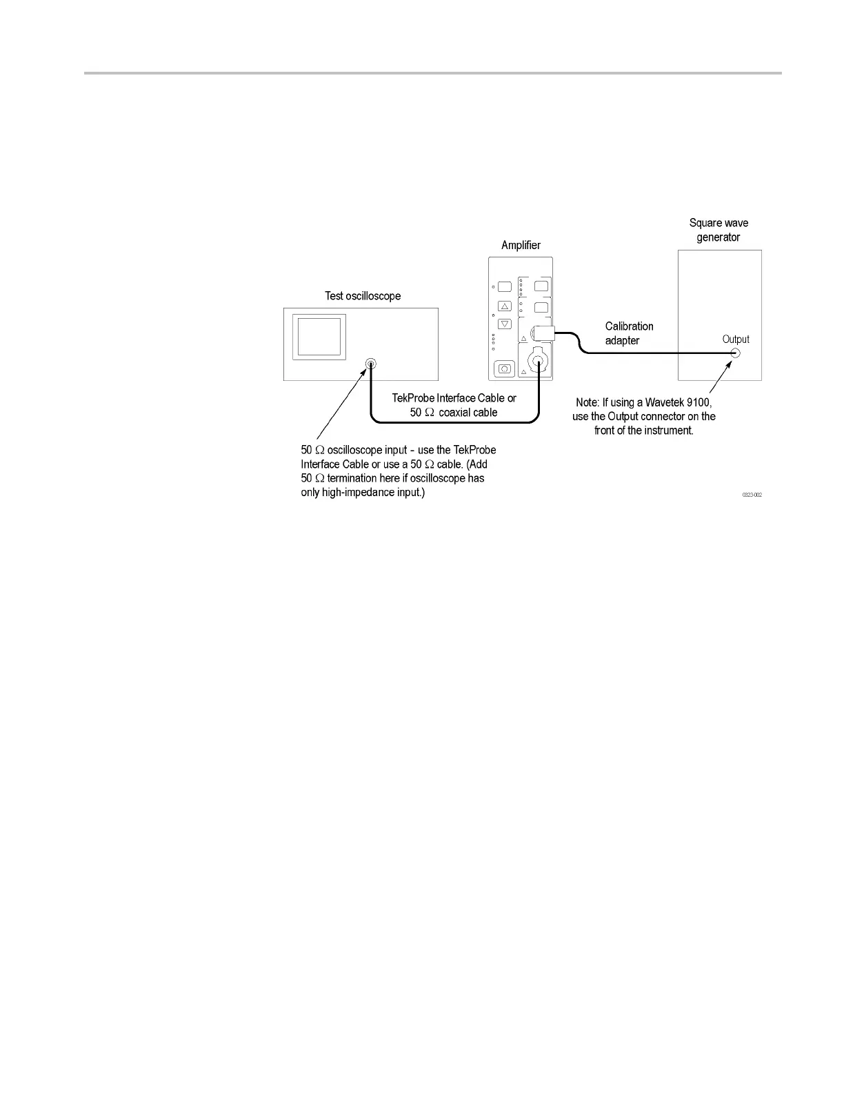
Figure 4: AC coupling test setup
To perform the check, do the following:
1. Connect the circuit as shown.
2. Set the amplifier COUPLING to DC.
3. If you are checking a TCPA300, set the RANGE to 1 A/V.
4. Set t
he generator to output a 28 Hz square wave.
5. Set the oscilloscope horizontal scale to 4 or 5 ms/div.
6. More equipment settings are available. (See Table 9 on page 14.)
7. Measure the signal on the oscilloscope and verify that it is 1Vp-p. If
necessary, adjust the generator output to achieve 1Vp-p.
8. Set the amplifier COUPLING to AC.
9. Measure the signal on the oscilloscope and verify that the signal is within
the limits on the test record.
TCPA300/400 Amplifiers and TCP300/400 Series Current Probes Service Manual 13

 Loading...

