TCPA300 and TCPA400 Performance Verification
Table 9: TCPA30
0 and TCPA400 AC coupling measurements
TEKPROBE Interface Cable BNC coaxial cable
Amplifier
Square
wave
generator
amplitude
Vertical
gain
setting
DC
coupled
amplifier
output
Minimum
AC
coupled
amplifier
output
Maximum
AC
coupled
amplifier
output
Vertical
gain
setting
DC
coupled
amplifier
output
Minimum
AC
coupled
amplifier
output
Maximum
AC
coupled
amplifier
output
TCPA300
0.5 Vp
200 mA/div
1.00 Ap-p 1.05 Ap-p 1.50 Ap-p
200 mV/div
1.00 Vp-p 1.05 Vp-p 1.50 Vp-p
TCPA400
0.5 Vp
200 A/div
1000 Ap-p 1050 Ap-p 1500 Ap-p
200 mV/div
1.00 Vp-p 1.05 Vp-p 1.50 Vp-p
10. Disconnect the Calibration Adapter from the amplifier.
Degauss
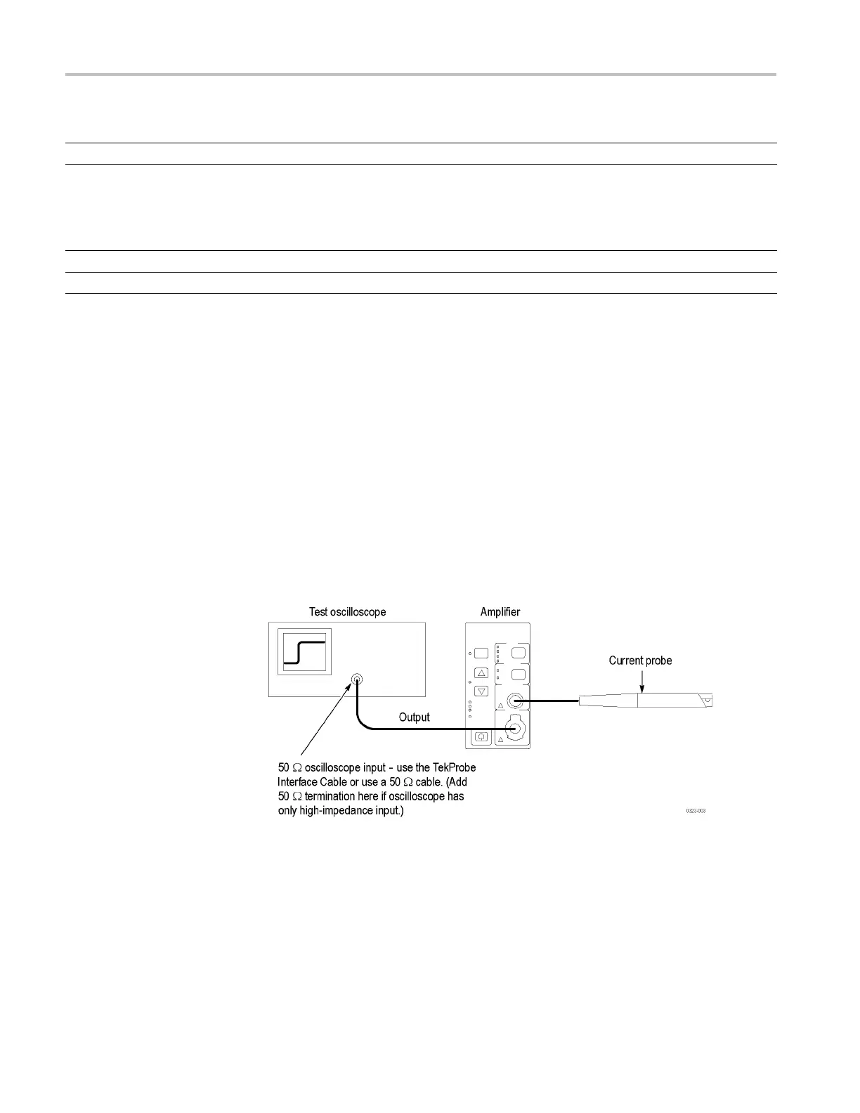
This is a functional test of the degauss operation. (See Figure 5.)
1. Connect a current probe to the output of the amplifier. Do not clamp the
current probe around any conductor, but make sure the jaws are locked shut.
2. Press the amplifier PROBE DEGAUSS AUTOBALANCE button. When the
indicator turns green, the degauss operation has successfully completed.
3. Verify that there are no error codes. Error codes display on the Probe Status
LEDs when the AC and DC COUPLING LEDs alternately flash.
4. Record the results (pass/fail) on the test record.
Figure 5: Setup for degaussing the current probe
14 TCPA300/400 Amplifiers and TCP300/400 Series Current Probes Service Manual

 Loading...

