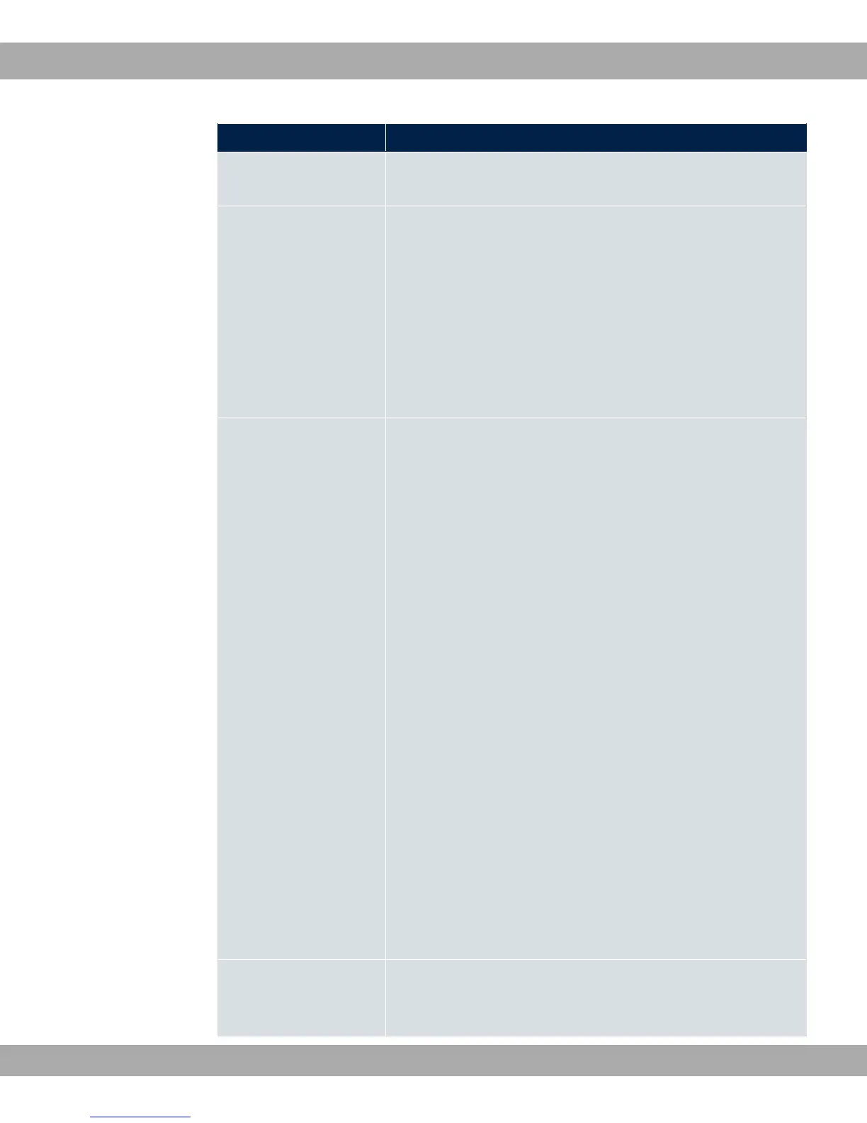
Field Description
• -< = (default value): For applications in Europe
(provider-dependent) for example.
Clock Rate Define whether the clock rate should be negotiated.
Possible values:
• 9<: The clock rate is predefined.
• -) (default value): The clock rate is negotiated de-
pending on the line quality.
Note that a fixed value must be set to use the IMA mode (see
8 %) on at least one side (CO or CPE).
Wire Mode Define the number and combination of wires (depending on the
device type) used for the SHDSL connection.
Possible values:
• 1: Two wires are used with m-pair bonding for a clock
rate of 192 kbps to 5696 kbps.
• 1: Four wires are used with m-pair bonding for a clock
rate of 384 kbps to 11392 kbps. This option supports 4-wire
mode under G991.2 and Globespan Enhanced Mode.
• 1 #: Four wires are used for m-pair bonding
with a clock rate of 384 kbps to 11392 kbps. This option sup-
ports 4-wire mode under G991.2 but not Globespan En-
hanced Mode.
• 1 %-: 4 wires are used with IMA for a clock rate of
384 kbps to 11392 kbps.
• 1: 6 wires are used with m-pair bonding for a clock rate
of 576 kbps to 17088 kbps.
• 1 %-: 6 wires are used with IMA for a clock rate of
576 kbps to 17088 kbps.
• 1: 8 wires are used with m-pair bonding for a clock rate
of 768 kbps to 22784 kbps.
• 1 %-: 8 wires are used with IMA for a clock rate of
768 kbps to 22784 kbps.
Additional Wire Pairs Only for Wire Mode = 1, 1 #, 1
%-, 1, 1 %-.
Teldat GmbH
11 Physical Interfaces
bintec Rxxx2/RTxxx2 143
 Loading...