Installation Model 7600
Teledyne Analytical Instruments 26
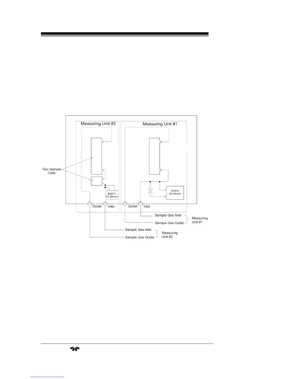
An internal piping diagram for an instrument with one or two
measuring units is shown in Figure 2-4. When there are two measuring
units, if a built-in oxygen sensor is used, it must be installed in
measuring unit 2. The diagram shows the combination of two cells used
in measuring unit #2. This is possible by combining ranges. When a
single measuring unit is used, there is only a single inlet and outlet gas
connection.
Figure 2-4: Internal Piping with Single or Dual Measuring Units
Depending on the options chosen, the analyzer can be configured in
several ways. Table 2-1 lists the possible configurations for single and
dual measuring units with 1 to 4 component meters.


 To Next Page