Infrared Gas Analyzer Installation
Teledyne Analytical Instruments 33
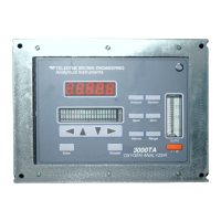
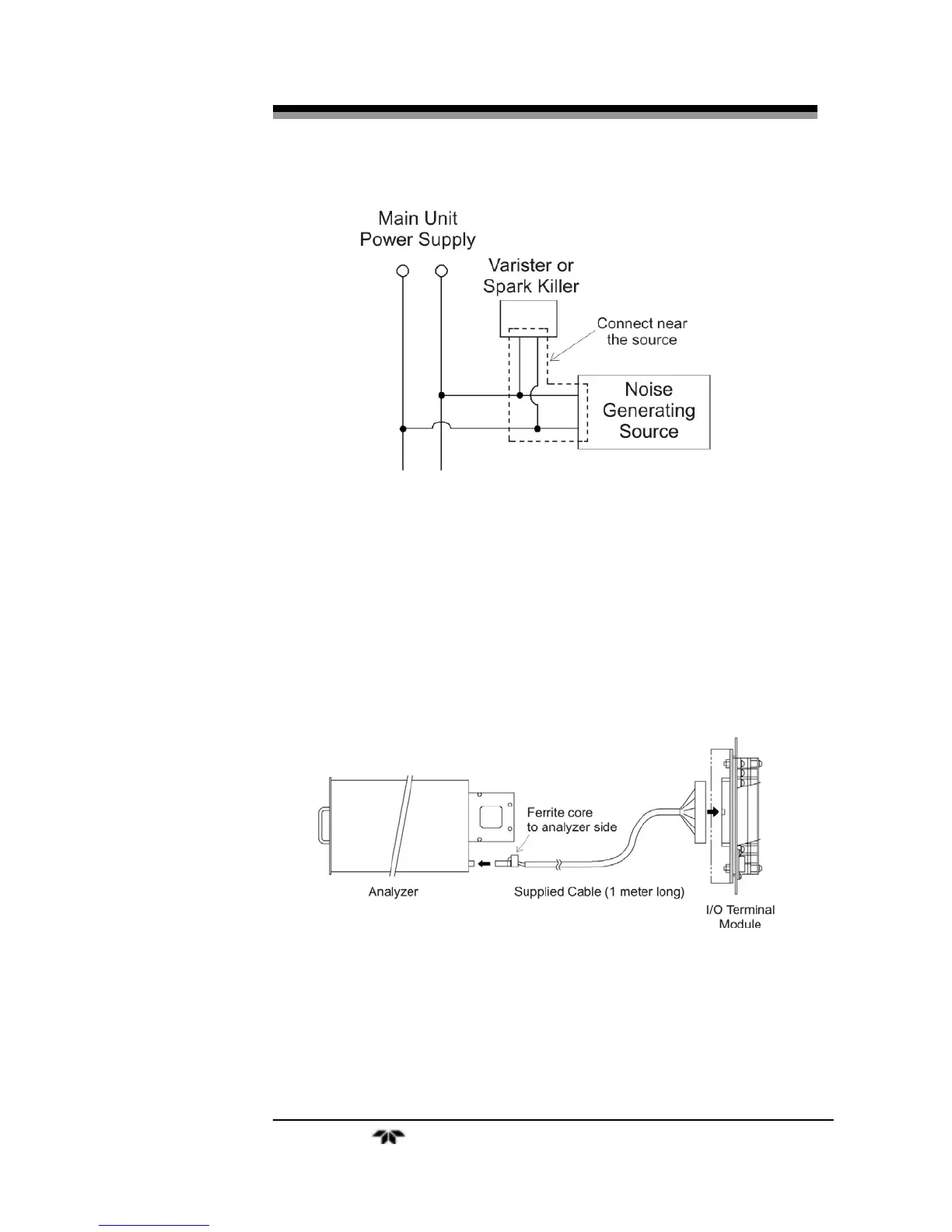
Figure 2-10: Noise Suppression
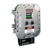
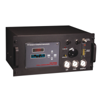
2.6.2 Input/Output Terminal Module
Use the supplied cable to interface the I/O Module to the analyzer.
Plug the cable connector into the receptacle at the rear panel of the
analyzer and the receptacle on the PC board of the input/output module.
Make sure that the ferrite core attached to the I/O cable goes to the
analyzer. See Figures 2-9 and 2-11.
Figure 2-11: I/O Cable Connection
The I/O Module carries various input and output signals. A detailed
list of these signals and pinout information is given in the Appendix.
 Loading...