Q-Flex Satellite Modem Installation and Operating Handbook
6-69
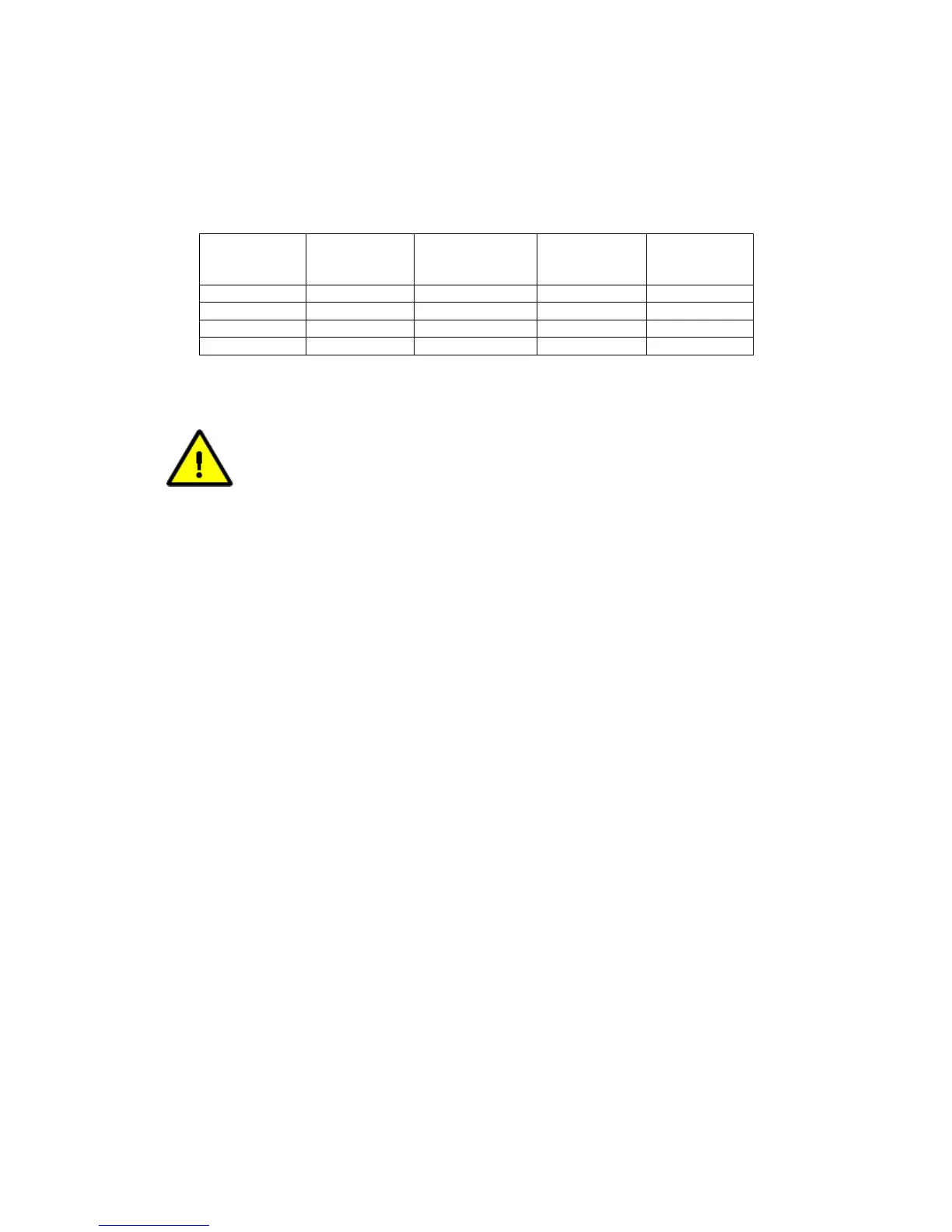
Table 6-73 indicates the circumstances under which modem signal inversions are
required in relation to Paired Carrier™ operation.
Carrier
Working?
BUC LNB
Tx Modem
Inversion
Rx Modem
Inversion
Yes Non Inverting Non Inverting No No
Yes Non Inverting Inverting No Yes
Yes Inverting Inverting No No
No Inverting Non Inverting N/A N/A
Table 6-73 Paired Carrier™ Spectral Inversion Control
PLEASE READ THE FOLLOWING INFORMATION FOR FIRST-TIME
SETUP OF A PAIRED CARRIER™ LINK.
In relation to Paired Carrier™, generally there are no restrictions on how
the overlapped carriers are brought up and the satellite link is established.
However, the following guidelines may be useful in proving correct Paired
Carrier™ operation as part of the overall initial link deployment process.
Once correct operation is established then Paired Carrier™ can be
switched on and off or reconfigured just like any other modem feature.
You must get each link working correctly as a normal link prior to
switching Paired Carrier™
on! You must ensure that there is no spectral
inversion in the RF chain – if there is then this must be corrected by re-
inverting it for Paired Carrier™ operation to work – see the above table.
1. Ensure Paired Carrier™ is switched off (via the Paired Carrier enable
setting on the Edit->Paired Carrier menu).
2. Before starting, it is strongly recommended to prepare for a BER data
transparency test, using data test sets connected to each modem, or
using the modem internal PRBS BER test feature, which can be
temporarily enabled if necessary.
3. Configure both modems for identical services, including the same Tx
and Rx frequencies.
Different PRBS test patterns must be used in each direction (e.g. for
Modem 1 Tx to Modem 2 Rx use 2^15-
1 and for Modem 2 Tx to Modem 1
Rx use 2^23-1). This ensures that the two signals ar
different from each other to allow Paired Carrier™ to work.
4. Check the Tx power level setting is correct and bring up the first carrier
(using the selected common transmission frequency) and
• Check the receive signal level, Eb/No, spectrum and
constellation are as expected.
• Check the received signal is data transparent.
5. Switch the first carrier off.
6. Check the Tx power level setting is correct and bring up the second
carrier (using the selected common transmission frequency) and