5.5 Front Panel
Figure 5-1 Modem Front Panel
The front panel, shown in Figure 5-1, comprises:
• Light Emitting Diodes (LEDs) that provide basic modem status.
• A Liquid Crystal Display (LCD) that acts as the local user interface.
• A keypad for menu navigation and alphanumeric entry.
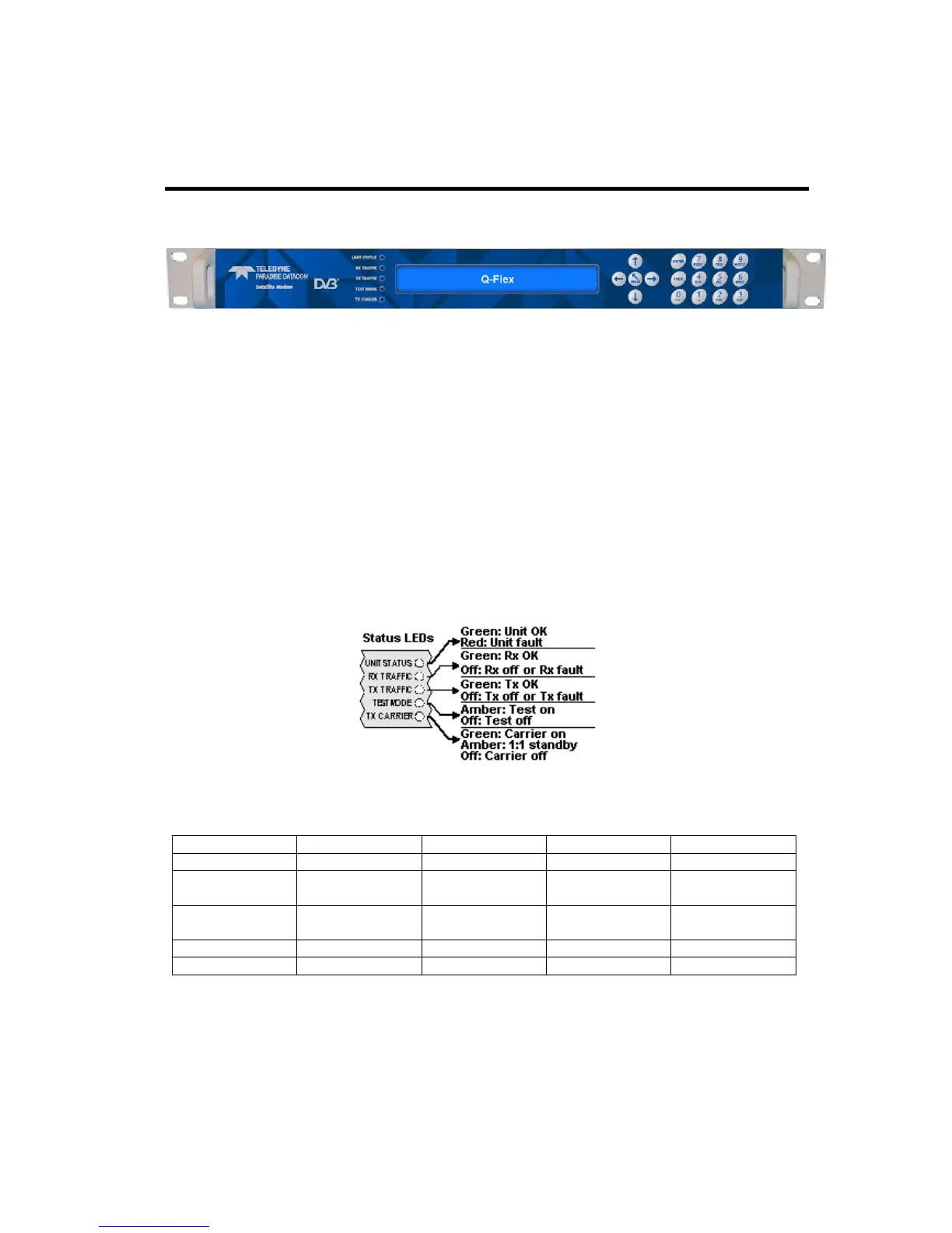
5.5.1 Status Indicators
The five front-panel LEDs display warning and fault information as shown in Figure 5-2
and as described in Table 5-3.
Figure 5-2 Front-panel Status Indicators
Carrier muted
Not used
1:1 standby Carrier active
Table 5-3 Front-panel LED Status
5.5.2 LCD Display
The backlit LCD is a graphical display formatted to give three lines of 40 text characters
and is highly legible even in strong ambient light. The contrast is adjustable and the
backlight can be dimmed or brightened as required.
 Loading...