Each route consists of a destination IP address and subnet mask. The Add and Del
buttons enable and disable each route, respectively. Note that routes can be applied even
when in bridging mode.
The Click to apply routes button must be selected to apply the header compression
routes before navigating away from the web page.
The Show Routes button can be used to confirm the active header compression routes.
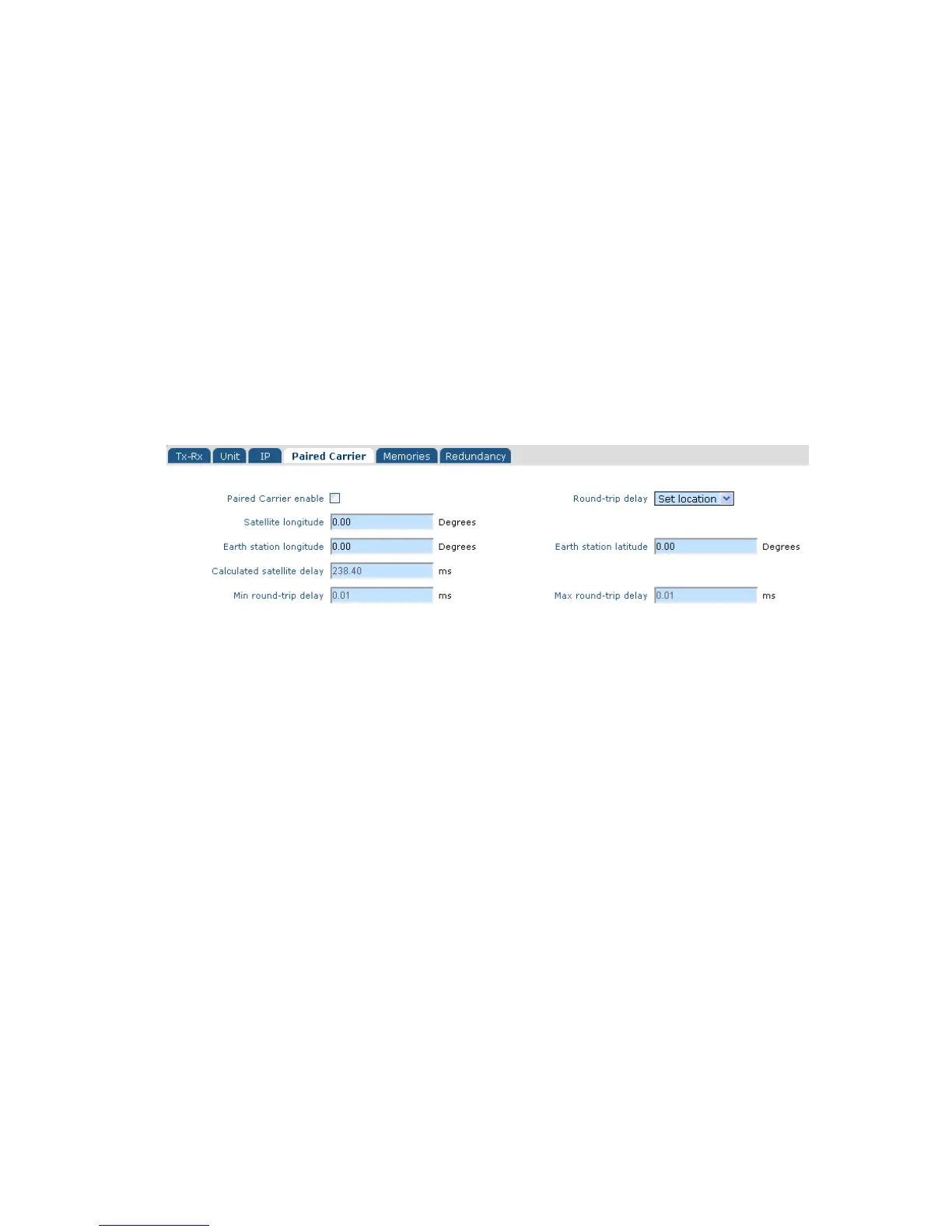
6.2.7 Edit->Paired Carrier Screen
The Edit->Paired Carrier screen (shown in Figure 6-26) is used to set up the Paired
Carrier™ function, which allows two carriers to be overlapped in the same space segment.
Figure 6-26 Edit->Paired Carrier Screen
6.2.7.1 Paired Carrier Enable
This is an On/Off control that enables and disables Paired Carrier™ operation.
Deployment recommendations for first-time use of Paired Carrier™ are provided in
the information box on the next page.
When switched on, the modem expects the received signal to consist of two overlapped
carriers utilizing the same space segment. When active, a copy of the modem’s
transmitted signal will be stored in memory and the Paired Carrier™ signal processing
algorithm will attempt to match this with the composite return signal, in order to subtract
the unwanted near signal leaving just the far carrier.
Prior to enabling Paired Carrier™ it is necessary to set up the delay to satellite as in the
following menu options.
Note that there are no other control settings that are specific to Paired Carrier™
operation – other settings used by the Paired Carrier™ algorithm such as centre
frequency and sweep width form part of the normal setup of the modem even for non-
overlapped carriers and work in the same way. The cancellation bandwidth itself is
automatically deduced by the modem from the larger of the transmit and receive symbol
rates and roll-off factors (i.e. occupied bandwidth).