ADR-7000 / SAVER-7000 / GUARD-7
© 2017 – Telefire Fire & Gas Detectors Ltd Revision 0.98 October 2017
– Page 26 of 87 –
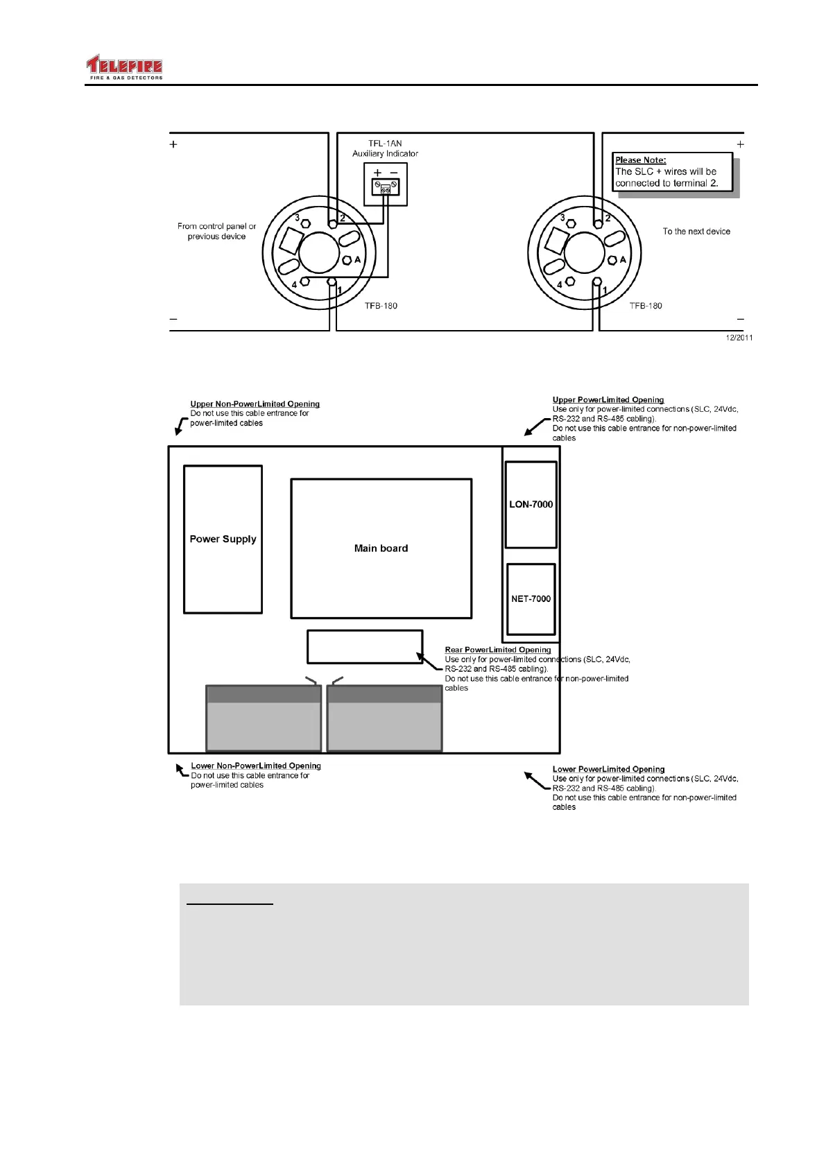
Figure 12 Example connection – detectors
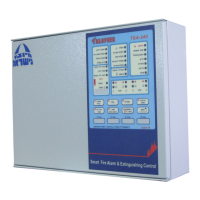
Figure 13 ADR-7000 cable routing
4.4.4 Connecting Low-Voltage Devices
Warning
Measure the wiring to ensure there are no shorts or ground faults prior
to connecting field cabling to the control panel.
Connection or adding loops, i/o modules, detectors, etc., will be
performed when all power supply sources (mains and batteries) are
disconnected.
Connect the loops, 24Vdc supply to field, control panel outputs (dialer, NACs, relays),
remote annunciators, and other panels, as applicable. See Figure 7 and Figure 8 for
field connection diagram.