TMP4100-Series Installation/Maintenance
33480D01.DOC 1-11
Change 1
1.5.1 Marking Head Installation
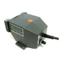
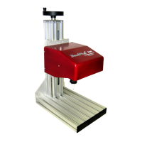
Refer to Figure 1-1 for general arrangement. For hand-held units, refer to Figure 1-2 for dimensions.
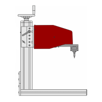
For fixture-mounted units, refer to Figure 1-3 for mounting hole dimensions and locations.
TMP4100:
1. To allow the marker cable to reach the controller, ensure the marking head location is within 4m (13 ft.)
of the proposed controller location.
2. Connect the drive air (black) tubing to the drive air fitting on the marking head.
3. Proceed with Filter/Regulator Unit Installation.
TMP4100E:
1. To allow the marker cable to reach the controller, ensure the marking head location is within 4m (13 ft.)
of the proposed controller location.
2. Proceed to Controller Installation.
TMP4150, TMP4155: (optional – plumbing for internal air pressure)
The marking head can be plumbed to receive internal air pressure. Positive air pressure within the marker will
help prevent contaminants from entering the marking head cavity.
Note: If the marking head will not be plumbed, proceed to TMP4150, TMP4155 Mounting Instructions.
1. Remove three socket head cap screws that attach mounting plate to marker top plate; remove mounting plate.
2. Remove marking head cover. Lift up on tabs of latches located on sides of marker. Rotate tabs counter-
clockwise to loosen and disengage latches. Slide protective boot over end of cartridge. Slide cover off marker.
3. Locate plug in top plate (adjacent to elbow fittings). Remove plug from top plate.
4. Locate set screw in top plate (adjacent to marker exhaust port). Remove set screw.
5. Fabricate positive pressure air fitting:
a. Obtain one 90° elbow fitting (26964) and 1½" length of 6mm air tubing (26506).
b. Install elbow fitting in top plate (where plug was removed). Install fitting such that 90° elbow is on
inside
of plate and oriented along edge of top plate and away from existing elbow fittings.
c. Using a heat gun, heat one end of 6mm air tubing until pliable, then crimp closed
.
d. Insert open end of tubing into elbow fitting; seat completely.
e. Drill one .012" orifice in exposed length of tubing. Rotate orifice toward back plate
.
6. Install marking head cover. Slide cover over marker. Engage latches and rotate tabs clockwise to tighten.
Push down on tabs so they lay flat against sides of marker. Slide protective boot up, onto cartridge.
7. Apply
LOCTITE
®
242 to three M6-1.0 x 12mm socket head cap screws. Use cap screws to attach
mounting plate to top plate.
CAUTION
Never apply more than 2.0 psi (0.13 bars) air pressure to internal cavity of marking head.
8. Attach tubing from positive pressure air source to newly installed bulkhead fitting.
9. If the marker will operate in a wet environment, plumb the case vent to clean, dry air:
a. Install one M-5AU-6 barbed fitting (30793) into threaded hole in mounting plate (above hole where set
screw was removed from top plate and adjacent to marker exhaust port).
b. Attach sufficient length of air tubing (26506) to barbed fitting and route tubing to clean, dry air.
10. Proceed with TMP4150, TMP4155 Mounting Instructions.