TMP4100-Series Installation/Maintenance
2-10 33480D01.DOC
2.6 TESTING PROCEDURES
This section provides reference tables to check the circuitry for TMP4100-Series marking heads.
2.6.1 Stepper Motor Resistance
The following information is provided to check the resistance values of the stepper motor circuit.
1. Remove electrical power from the marking system.
2.
TMP4100, TMP4150, TMP4155: Remove air pressure from the marking system.
3. Disconnect the marker cable from the controller.
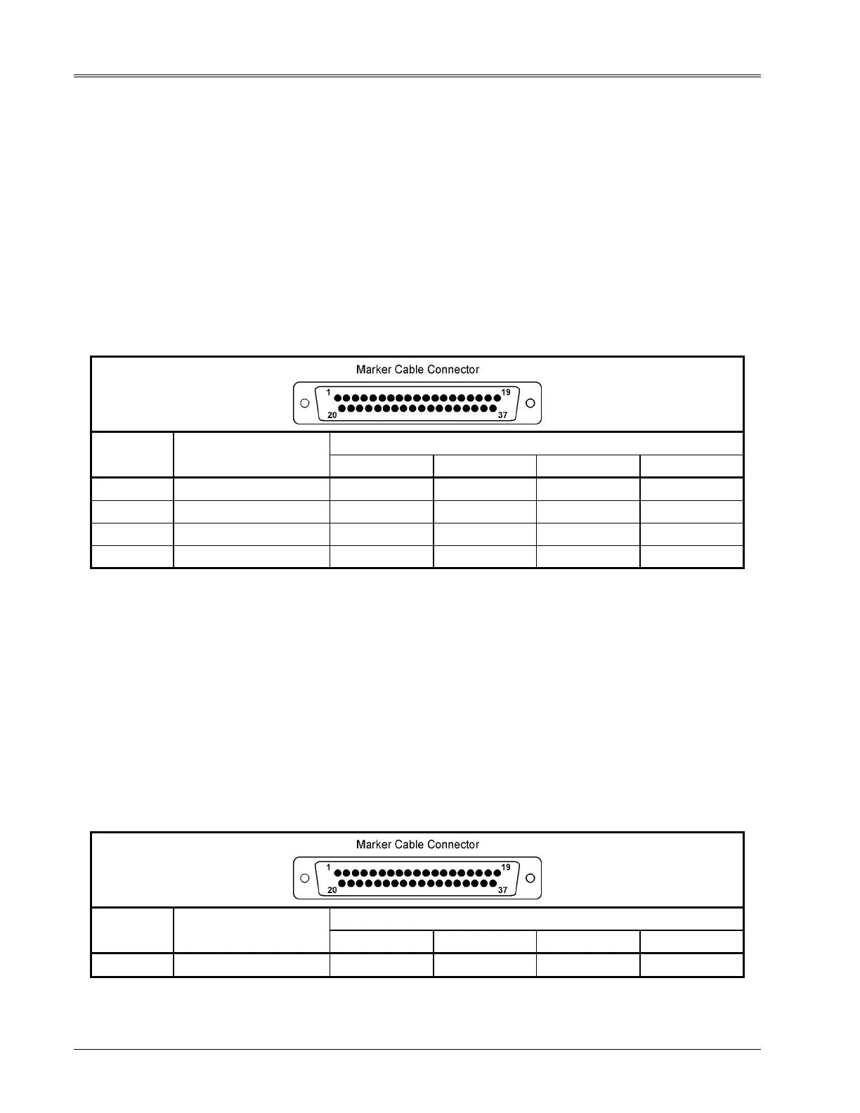
4. Measure the resistance values for the stepper motor at the connector on the end of the marker cable.
Refer to Table 2-2 for acceptable values.
Table 2-2. Stepper Motor Resistance Checks
RESISTANCE VALUE
PIN-TO-PIN DESCRIPTION TMP4100 TMP4100E TMP4150 TMP4155
1 to 2 X-AXIS MOTOR PHASE A 2.0 ohms ±10% 2.0 ohms ±10% 2.0 ohms ±10% 2.0 ohms ±10%
3 to 4 X-AXIS MOTOR PHASE B 2.0 ohms ±10% 2.0 ohms ±10% 2.0 ohms ±10% 2.0 ohms ±10%
5 to 6 Y-AXIS MOTOR PHASE A 2.0 ohms ±10% 2.0 ohms ±10% 2.0 ohms ±10% 2.0 ohms ±10%
7 to 8 Y-AXIS MOTOR PHASE B 2.0 ohms ±10% 2.0 ohms ±10% 2.0 ohms ±10% 2.0 ohms ±10%
2.6.2 Solenoid Resistance
The following information is provided to check the resistance values of the solenoid circuit.
1. Remove electrical power from the marking system.
2.
TMP4100, TMP4150, TMP4155: Remove air pressure from the marking system.
3. Disconnect the marker cable from the controller.
4. Measure the resistance values for the solenoid at the connector on the end of the marker cable.
Refer to Table 2-3 for acceptable values.
Table 2-3. Solenoid Resistance Checks
RESISTANCE VALUE
PIN-TO-PIN DESCRIPTION TMP4100 TMP4100E TMP4150 TMP4155
9 to 12 SOLENOID #1 12 ohms ±5% 8.4 ohms ±5% 38 ohms ±5% 38 ohms ±5%