TMP4100-Series Installation/Maintenance
2-18 33480D01.DOC
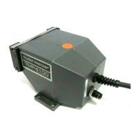
2.8.4 TMP4100E Solenoid Valve
Perform the following procedure to replace the TMP4100E solenoid valve.
Removal
1. Remove electrical power from the marking system.
2. Remove the impact pin / pin cartridge from the marking head. (see replacement procedure)
3. Remove the standoffs. (see replacement procedure)
4. Using a 2.5mm hex key, remove four M3-0.50 x 25 screws securing right cover to left cover.
Separate covers and place right cover aside.
5. Using a 2mm hex key, loosen set screw in handle holding the push button switch.
6. Remove switch connector J2 from the limit board.
7. Remove the switch assembly from the handle.
8. Using a 2.5mm hex key, loosen set screw securing the handle to the handle mount.
Gently, pry and pull handle from the mount.
9. Using a 3mm hex key, remove two M4-0.70 x 16 socket head cap screws that secure the handle mount to
the manifold base.
10. Remove cable connector J1 from the limit board and disconnect the ground lug.
11. Using a 2.5mm hex key, remove three flat head screws from the bottom of the left cover.
12. Remove the marking unit from the left cover and place left cover aside.
13. Disconnect connectors on J6 and J7.
14. Remove two M3-.05 x 6mm flat head cap screws from the electric pin. Remove the armature and
shim(s).
15. Rotate the solenoid over the end leg.
16. Remove two M3-.05 x 6mm flat head cap screws that secure the solenoid frame to the cartridge base.
17. Remove two nuts securing solenoid to the electric pin base.
18. Note wire routing and location of wire ties. Remove wire ties, as applicable, and remove solenoid.
Installation
1. Mount the solenoid to the electric pin base using the two nuts provided on the solenoid.
2. Thread the wires from the solenoid through the hole in the face of the cartridge base leaving about 1½ to
2 inches protruding from the face.
3. Place the solenoid frame on the face of the cartridge base with wires through the notches and on top.
Align the screw holes and attach with two M3-.05 x 6mm flat head cap screws.
4. Rotate the solenoid over the end of the leg so that wires are on either side of the top leg. Push the
assembly down between the legs, solenoid first.