TMP4100-Series Installation/Maintenance
33480D01.DOC 2-11
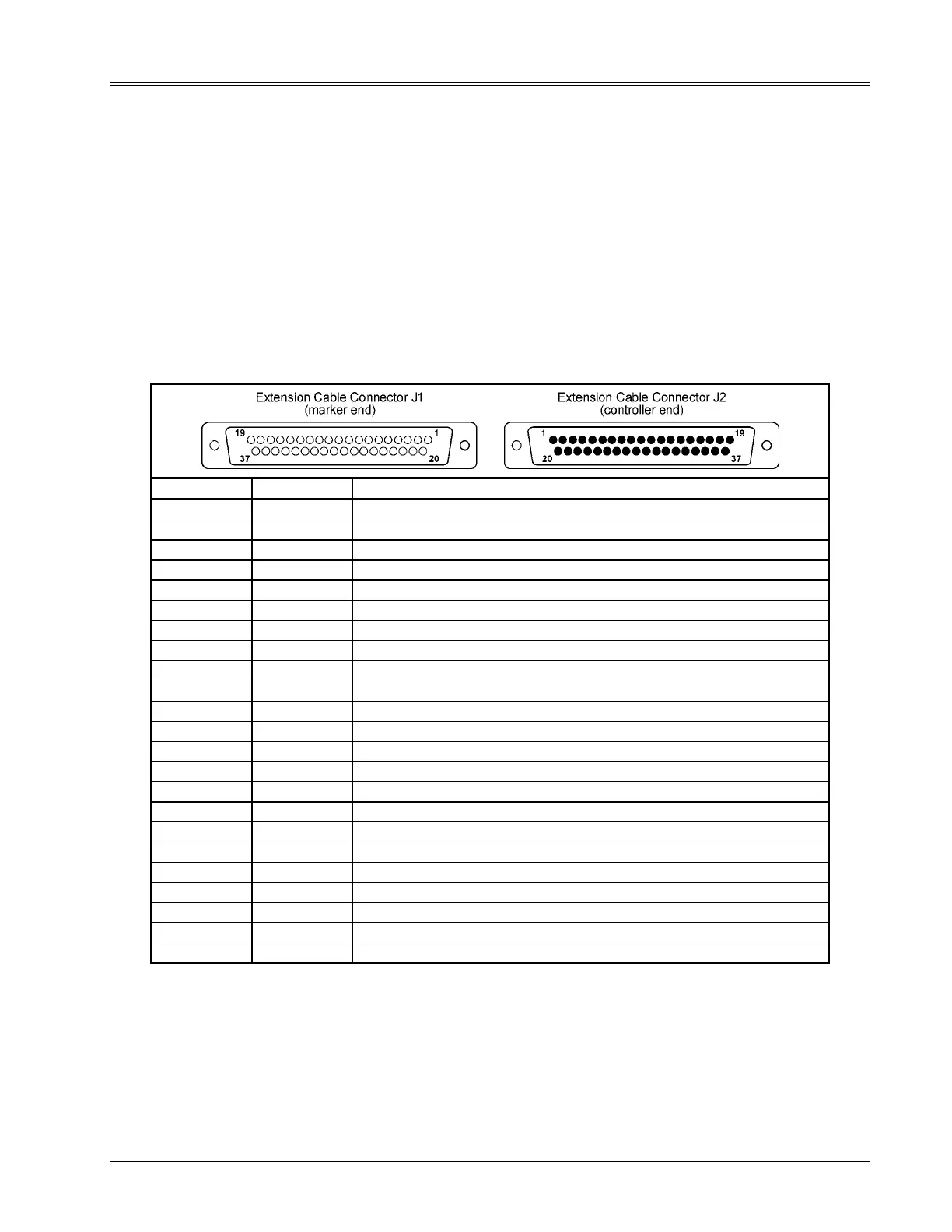
2.6.3 Extension Cable Continuity
The following information is provided to check the continuity of the marking head extension cable, if used.
The cable connects between the TMP4100-Series marker cable and the controller.
1. Remove electrical power from the marking system.
2.
TMP4100, TMP4150, TMP4155: Remove air pressure from the marking system.
3. Disconnect the extension cable from the marker cable.
4. Disconnect the extension cable from the controller.
5. Check the pin-to-pin continuity of the extension cable.
Refer to Table 2-4 for pin numbers and signal information.
Table 2-4. Marking Head Extension Cable Pin Assignments
FROM J1 TO J2 FUNCTION
1 1 X MOTOR PHASE 1
2 2 X MOTOR PHASE 2
3 3 X MOTOR PHASE 3
4 4 X MOTOR PHASE 4
5 5 Y MOTOR PHASE 1
6 6 Y MOTOR PHASE 2
7 7 Y MOTOR PHASE 3
8 8 Y MOTOR PHASE 4
9 9 SOLENOID COMMON
10 10 SOLENOID COMMON
12 12 SOLENOID #1 (Impact Pin, TMP4100-Series markers)
13 13 SOLENOID #2 (Impact Pin, TMP4100E only)
14 14 SOLENOID #3 (Impact Pin, TMP4100E only)
15 15 SOLENOID #4 [not used w/ standard TMP4100-Series markers]
16 16 SOLENOID #5 [not used w/ standard TMP4100-Series markers]
17 17 SOLENOID #6 [not used w/ standard TMP4100-Series markers]
20 20 +5 VDC RETURN
21 21 + 5 VDC
22 22 X HOME
25 25 Y HOME
28 28 START PRINT – (+5 VDC RETURN)
29 29 START PRINT +
37 37 CHASSIS GROUND