TMP4100-Series Installation/Maintenance
1-16 33480D01.DOC
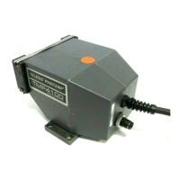
1.5.2 Filter/Regulator Unit Installation
TMP4100E: The TMP4100E does not use air pressure to drive the marking pin. The following section does
not apply to the TMP4100E marker.
TMP4100, TMP4150, TMP4155:
1. To allow the air lines to reach the marking head, ensure the filter/regulator mounting location is within
12 ft. (3.6m) of the marker location.
2. Refer to the Original Equipment Manufacturer (OEM) drawing for filter/regulator unit mounting details.
3. Rotate the drive air pressure adjustment knob fully counter-clockwise.
4.
TMP4150, TMP4155: Rotate the return air pressure adjustment knob fully counter-clockwise.
5. Mount the filter/regulator unit vertically to a solid, stable surface.
6. Secure the filter/regulator unit using four M4 (#8) fasteners.
7.
TMP4100: Connect the drive air (black) from the marking head to the filter/ regulator unit.
8.
TMP4150, TMP4155: Connect the drive air (black) from the marking head to the filter/ regulator unit.
Note: The Drive Air fitting on the filter/regulator unit is the tee fitting between the two regulators.
9.
TMP4150, TMP4155: Connect return air (natural) tubing from the marking head to the filter/ regulator unit.
Note: The Return Air fitting on the filter/regulator unit is the elbow fitting at the right side of the unit..
10. Install a supply inlet fitting in the left-side of the filter/regulator unit.
11. Ensure the supply air is shut off upstream of the filter/regulator unit.
12. Connect the supply air line to the filter/regulator unit inlet fitting.
DO NOT apply inlet (supply) air pressure to the filter/regulator unit at this time.
13. Proceed with Controller Installation.