64 MA365 • Rev. A2
Tellabs
®
6325 Edge Node 3 Reference Information
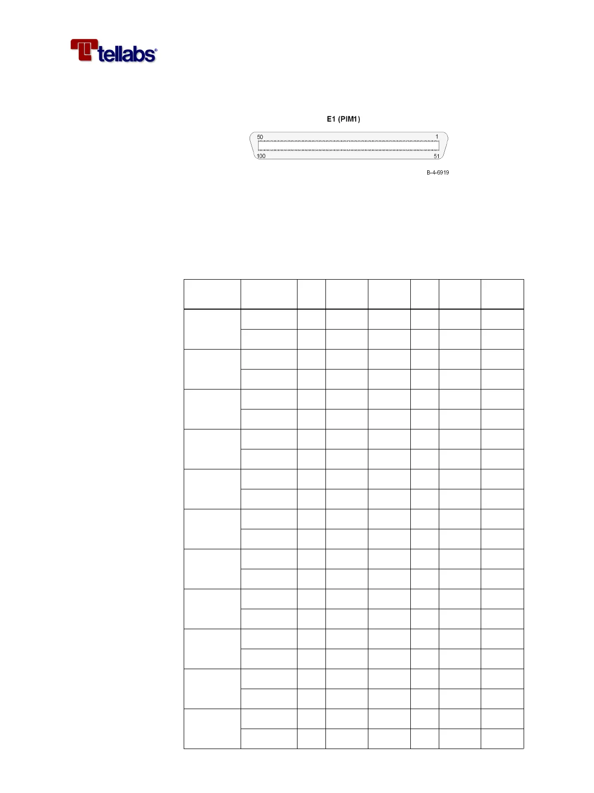
Pin designations on
PIM1 connector and
color coding of the E1
cable
The figure shows the E1 connector on the PIM1 module.
The pin designation of the E1 connector on the PIM1 module and the color
coding of the E1 open ended cable (WK-503Y-zz.z-01) is listed in the following
table.
Note: The non-inverted signal is located at a pin in the upper row of the con-
nector and the inverted signal is located at the pin just below in the low-
er row of the connector. This means that signals on pin 1 and 51 is a pair,
signals on pin 2 and 52 is a pair and so on.
Channel Binder Pin signal
Solid
Color
Pin signal
Solid
Color
1 Red 1 RX1 Blue 51 RX1\ White
Red 2 TX1 Orange 52 TX1\ White
2 Red 3 RX2 Green 53 RX2\ White
Red 4 TX2 Brown 54 TX2\ White
3 Red 5 RX3 Grey 55 RX3\ White
Red 6 TX3 Blue 56 TX3\ Red
4 Blue 7 RX4 Blue 57 RX4\ White
Blue 8 TX4 Orange 58 TX4\ White
5 Blue 9 RX5 Green 59 RX5\ White
Blue 10 TX5 Brown 60 TX5\ White
6 Blue 11 RX6 Grey 61 RX6\ White
Blue 12 TX6 Blue 62 TX6\ Red
7 Green 13 RX7 Blue 63 RX7\ White
Green 14 TX7 Orange 64 TX7\ White
8 Green 15 RX8 Green 65 RX8\ White
Green 16 TX8 Brown 66 TX8\ White
9 Green 17 RX9 Grey 67 RX9\ White
Green 18 TX9 Blue 68 TX9\ Red
10 Yellow 19 RX10 Blue 69 RX10\ White
Yellow 20 TX10 Orange 70 TX10\ White
11 Yellow 21 RX11 Green 71 RX11\ White
Yellow 22 TX11 Brown 72 TX11\ White