UNIMASTER
5
– Rotate the barrel (3) to give 20 mm on the scale.
– Slacken the setting screw (9).
– Push the mobile stop (5) inwards out of the
way, allowing the instrument to be placed on the
setting gauge with the measuring arms on the
inside.
– Release the mobile stop.
– Swing the instrument in a small arc until the cor-
– Rotate the barrel (3) to give 250 mm on the
scale.
– Slacken the setting screw (9).
– Pull the mobile stop (5) out, allowing the ins-
trument to be placed on the setting gauge with
the measuring arms on the outside. If necessary,
place distance pieces between the setting gauge
and the measuring arms
– Release the mobile stop.
Note: do not remove the measuring arms after setting to zero!
3 SETTING THE MEASURING HEAD TO ZERO
rect contact point is found by observation of the
dial gauge (2). Rotate the barrel (3) to bring the
dial gauge pointer to zero.
– Tighten the lever (14).
– Set the scale barrel (4) to the size marked on the
setting gauge.
– Tighten the setting screw (9).
– Check for correct zero setting.
– Swing the instrument in a small arc until the cor-
rect contact point is found by observation of the
dial gauge (2). Rotate the barrel (3) to bring the
dial gauge pointer to zero.
– Tighten the lever (14).
– Set the scale barrel (4) to the size marked on the
setting gauge. Tighten the setting screw (9).
– Check for correct zero seting.
Fig. 9. Fig. 10.
3.1
Internal measurement
(Fig.9)
3.2
External measurement
(Fig.10)
Never push the instrument back against the mobile
stop.
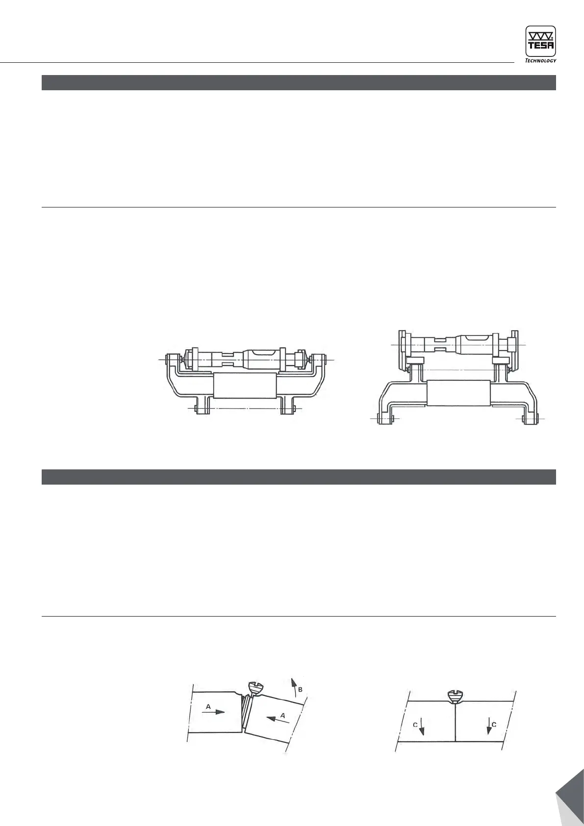
If several extensions are to be fitted, position these
in descending order of length, starting from the
measuring head.
– Slacken the nut (12) as far as possible.
– Clean the extension contact surfaces.
– Line up the nut (12) with the adjacent cutout, tilt
the two components as shown in Fig. 11, then
Never slacken more than one screw at a time!
– Slacken one of the nuts (12) as far as possible.
4 EXTENSIONS
snap them together by pressing in the direction
of arrow A and by moving in direction B.
– Lightly tighten the nut (12).
– Fit the following extensions in the same manner,
then finally the fixed stop.
– Align the supporting surfaces (11) by placing the
completed assembly on a flat surface.
– Tighten all nuts (12) to lock the snap rings.
– Break the joint by pulling in the direction of ar-
row C as shown in Fig. 12.
Fig. 11. Fig. 12.
4.1
Adding extensions
4.2
Separating the
extensions