EasyManua.ls Logo

TESA MICRO-HITE User Manual

TESA MICRO-HITE
163 pages
To Next Page IconTo Next Page
Page #1 background imageLoading...
Page #1 background image
V15 03.10.2017
1
Instruction manual
HEIGHT GAUGES
for MICRO-HITE (MH)
for MICRO-HITE+M (MH+M)
This document is confidential and only to be used internally by the company that has purchased one of the height gauges
mentioned above. Before duplicating or transmitting it to third parties without any connection to the use of these instruments,
an official request has to be sent to TESA SA.

Table of Contents

Question and Answer IconNeed help?

Do you have a question about the TESA MICRO-HITE and is the answer not in the manual?

TESA MICRO-HITE Specifications

General IconGeneral
Operating Temperature10 - 40 °C
Resolution0.001 mm
DisplayLCD
Power SupplyBattery
InterfaceRS232
Repeatability0.1μm
OutputRS232

Summary

1 INTRODUCTION

1.2 Warning

Crucial safety warnings for instrument use.

2 PRESENTATION

2.8 Electric power supply

Instructions and precautions for electrical power supply.

3 TECHNICAL SPECIFICATIONS

5 INSTALLATION, SECURITY & MAINTENANCE

5.7 Electric power supply

Guidelines and precautions for electrical power supply.

6 INSTALLATION

6.2 Unpacking & installation

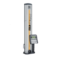
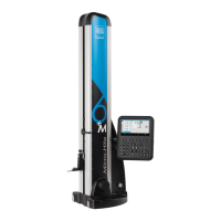
Detailed procedure for unpacking and initial installation.

7 CONTROL PANEL

7.4 Calculation zone

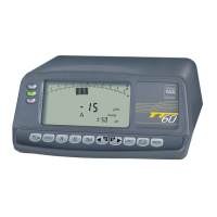
Explanation of the calculator zone functions.

8 MEASUREMENT INTERFACE

9 SYSTEM OPTIONS

9.2 System configuration

Settings for time, date, and initialisation mode.

9.3 Measurement parameters

Configuration of resolution, units, and speed.

9.4 Bore/axis, groove/rib measurement

Specific settings for bore, axis, groove, and rib measurements.

11 DETERMINATION OF THE PROBE CONSTANT

11.3 Procedure

General procedure for determining probe constant.

11.4 Steps

Detailed steps for probe constant determination.

12 PRINCIPLES OF MEASUREMENT

12.3 Measurement modes

Overview of available measurement modes (ST1, ST2, MAX, MIN, Δ).

12.4 ST1 & ST2 philosophy

Explains the difference and usage of ST1 and ST2 modes.

13 ST1 MODE

13.2 Capturing the reference value

How to capture reference values in ST1 mode.

14 ST2 MODE

14.2 Probe calibration

Procedure for calibrating the probe in ST2 mode.

14.3 Capturing the reference value

How to capture reference values in ST2 mode.

14.4 Single & double probing

Concepts of single and double probing.

15 MAX, MIN, Δ MODE

15.3 Measurement principle (MH+M)

Principle of measurement for angles on MH+M.

16 ANGLE MEASUREMENT

16.4 Cone angle measurement principle

Principle for measuring internal or external cone angles.

17 CALCULATOR

18 PERPENDICULARITY & STRAIGHTNESS MEASUREMENT

19 2D MODE

21 DATA MANAGEMENT

21.3 Transmission format

Defining the format for data transmission.

21.4 Transmission via TLC (cable)

Sending data to a computer using a TLC cable.

22 PROGRAM MANAGEMENT

22.2 Program creation

Process for creating new measurement programs.

22.3 Insert tolerances

How to insert tolerances into measurement blocks.

22.4 Tolerancing with ISO table

Using the ISO table for setting tolerances.

23 CONTROL AND UPDATES

23.4 Sensor control

Verifying sensor and scale positioning.

23.6 Software update

Procedure for updating the instrument's software.

Related product manuals