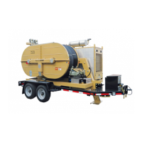
HYDRAULICPULLER‐TENSIONERPT2450
Tab
e:M
‐PT245
‐05
‐0
‐I
Data:0
.08.2018
utor:
M Page:11di11
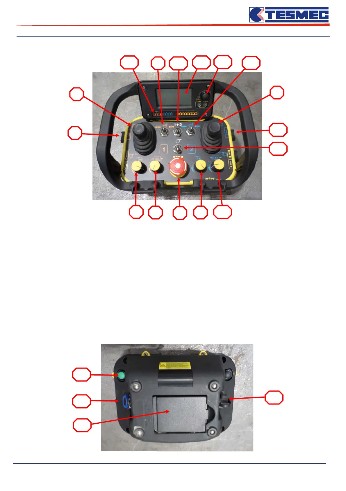
Table 9 – Machine Radio control
1. Operational stop button;
2. Joystick release/recovery circuit 1;
3. Pull force control circuit 1;
4. Reel winder control pressure circuit 1;
5. Rope clamp switch circuit 1;
6. -
7. Reel elevator rotation button circuit 1;
8. Joystick release/recovery circuit 2;
9. Pull force control circuit 2;
10. Reel winder control pressure circuit 2;
11. -
12. Rope clamp switch circuit 2;
13. Reel elevator rotation button circuit 2;
14. Active/inactive electronic connection;
15. Active/inactive syncronizer;
16. Alarm Led/or several reports;
17. Display data;
18. Page management display button e radio control
battery charge indicator;
19. Radio control connection button;
20. Switch on/off radio control;
21. Radio control battery;
22. Socket for remote connection cable.
1
2
8
3
94
10
5
12
13
7
14
15
16 17
18
19
20
21
22