HYDRAULIC PULLER TENSIONER PT2450
Manual: MI-PT2450-050-00-GB Date: 28.07.2018 Author: AT Page: 14 of 89
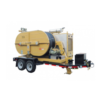
4.4 TOWING TRANSPORTATION
The machine is not arranged to be towed on the road.
Possible displacements on trailer in the working site must be carried out by a connection to the towing unit
by means of the towing eye on the drawbar (tab. 1) and in the respect of the speed limits of the axle. The
used towing unit must be homologated for towing trailers with mass and dimensions as per the described
machine.
Before transporting lift the rear stabilizers and the front plough (tab. 2, pos.1,5) through the dedicated
screen on the computer of the machine control (tab. 8, pos.1 and par.5.5.2.2 Machine Optional )
(NOTE: This must be done with the engine running).
Check the inflation pressure of tires (7 bars).
During machine transport operations, nobody must stay on the machine itself.
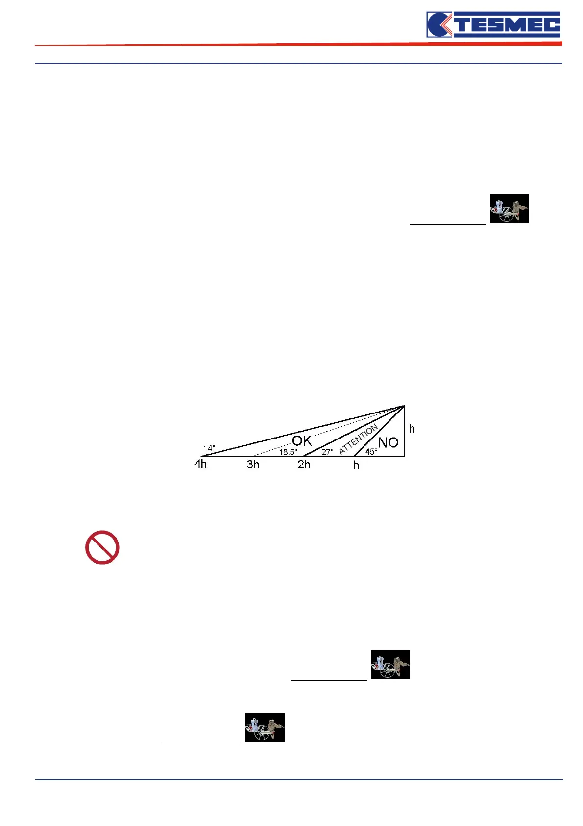
4.5 POSITIONING AND ANCHORING
Positioning and anchoring of the machine have to be carried out only by trained personnel, verifying if the
ground grants the foreseen stability, support and anchoring.
The machine has to be placed in a distance from the first pylon or trestle for the rope passage (or conductor)
included between 2 and 4 times the height h of the pylon itself (see diagram here below)
It is possible to use the machine at a distance from the pole included between 1 and 2 times the height of
the pole itself. In this case, the anchorage described thereafter must be over dimensioned of 125%
compared to the reported data and some moorings must be provided on the front side of the machine.
PROHIBITION
when the distance between the machine and the pole is lower than the height of
the pole itself, the machine use is not possible.
Machine anchoring sequence is the following:
a. keep the wheel brakes of the machine disengaged.
b. place the rear stabilizers as close to the ground through the dedicated screen on the computer of the
machine control (tab. 2, pos.5 and par.5.5.2.2 Machine Optional )
c. set the front plow through the dedicated screen on the computer of the machine control (tab. 2, pos.1
and par.5.5.2.2 Machine Optional ) in order to support the rear stabilizers to the ground,
thereby relieving the tires.