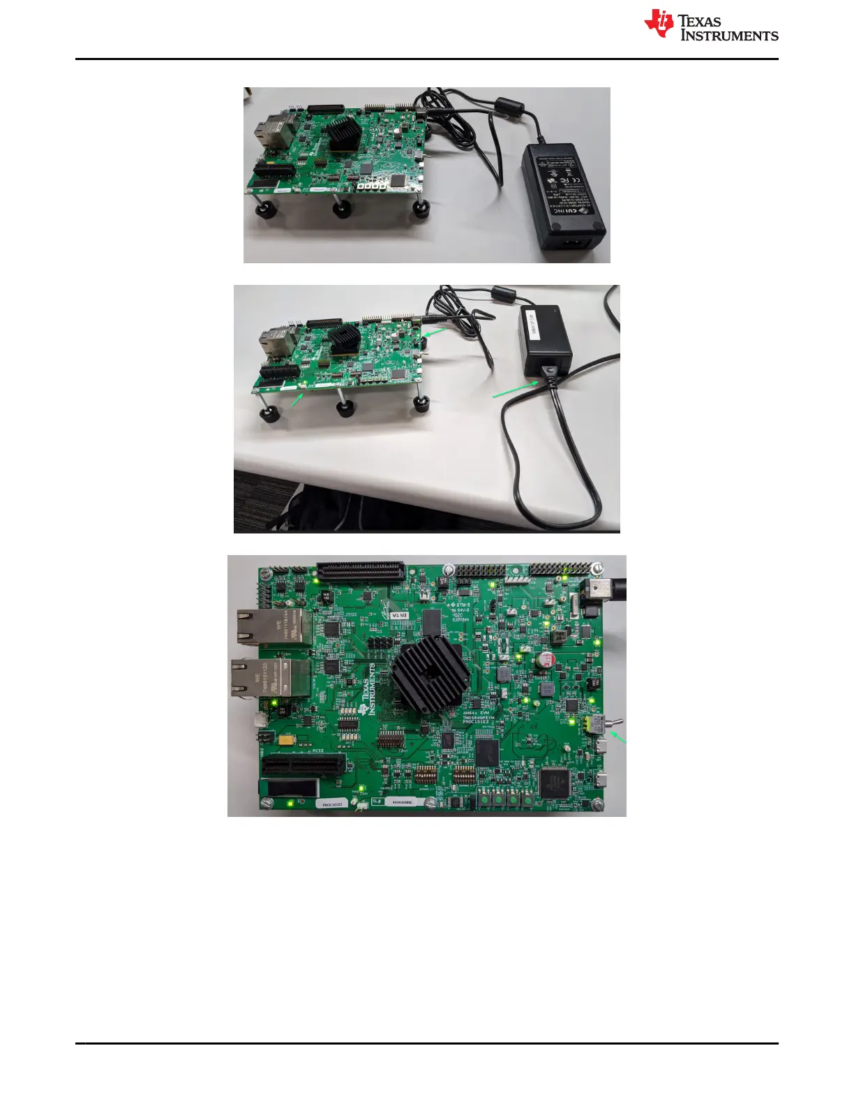
3. Attach 12 V AC/DC regulator plug to EVM power jack (J6), but do not power converter from AC power.
4. Apply AC power to AC/DC converter. 12 V power LED (LD6 and LD12) should illuminate.
5. Place EVM power (SW1) switch in ON position as shown below.
6. Visually inspect LED against reference photo above. The following LED should be illuminated:
• LD1, LD2, LD3, LD4, LD6, LD7, LD8, LD9, LD10, LD15, LD24, LD25
3.3.2 Power-Off Procedure
1. Switch EVM power switch (SW1) to OFF position.
2. Disconnect AC power from AC/DC converter.
3. Remove DC power plug from EVM power jack (J6).
System Description
www.ti.com
10 AM64x/AM243x GP EVM User's Guide SPRUIX0C – FEBRUARY 2021 – REVISED JUNE 2021
Submit Document Feedback
Copyright © 2021 Texas Instruments Incorporated

 Loading...


