3.4.17 Safety Connector
A 12x2 standard 0.1” spaced header- TSW-112-07-S-D is included as a safety signal connector. The safety
connector includes signals connected to the MCU. The 24 pins include MCU_I2C0, MCI_I2C1, MCU_UART1,
MCU_SPI0 and MCU_SPI1 signals. This provides eighteen signals that can be used as either the specified
interface or as MCU_GPIOs. In addition the CONN_MCU_RESETz, CONN_MCU_PORz, MCU_RESETSTATz
and MCU_SAFETY_ERRORn signals are supported with the connector.
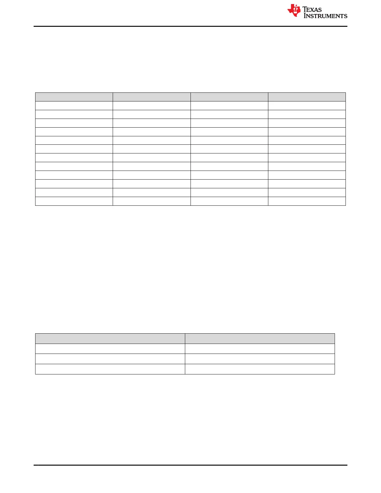
Table 3-27. Safety Connector Pinouts
Pin No. Signal Pin No. Signal
1 VCC_3V3_SYS 13 MCU_UART1_RTS_3V3
2 MCU_SPI0_D1 14 MCU_I2C1_SDA
3 MCU_SPI0_CS1 15 MCU_UART1_TX_3V3
4 MCU_SPI0_D0 16 MCU_SPI0_CLK
5 MCU_GPIO0_8 17 MCU_I2C0_SDA
6 MCU_SPI0_CS0 18 MCU_I2C1_SCL
7 TEST_LED2 19 MCU_RESETSTATZ
8 MCU_GPIO0_6 20 MCU_I2C0_SCL
9 MCU_GPIO0_7 21 CONN_MCU_RESETZ
10 MCU_UART1_CTS_3V3 22 MCU_SAFETY_ERRORZ_3V3
11 MCU_UART1_RX_3V3 23 DGND
12 MCU_GPIO0_9 24 CONN_MCU_PORZ
3.4.18 SPI Interfaces
• SPI0: A 1Kbit SPI EEPROM (93LC46B) is interfaced to SPI0 port of the AM64x/AM243x. It is used for testing
purposes.
• SPI1: This interface is routed to the HSE Connector. The SPI1 interface signals are at a 3.3 V IO level.
– SPI1_CS0 is routed to the HSE expansion header (J2)
– SPI1_CS1 is routed to the HSE expansion header (J2)
3.4.19 I2C Interfaces
There are five I2C interfaces used in the GP EVM board.
1. MAIN_I2C0: This interface is used by the software to identify the EVM and to control the power supply
circuit. It is interfaced to presence detect latch to identify the daughter cards which are presently installed,
Board ID memory device, board ID memories of the daughter cards and HSE connector. This I2C is also
connected to a test header J5 for AM64x/AM243x processor slave operation. Pin outs of I2C test header is
given in Table 3-28.
Table 3-28. I2C Test Header (J5) Pin-out
Pin No. Signal
1 DGND
2 SoC_I2C0_SDA
3 SoC_I2C0_SCL
System Description www.ti.com
56 AM64x/AM243x GP EVM User's Guide SPRUIX0C – FEBRUARY 2021 – REVISED JUNE 2021
Submit Document Feedback
Copyright © 2021 Texas Instruments Incorporated

 Loading...


