Table 3-20. Default Strap Setting of ICSSG Ethernet PHYs......................................................................................................36
Table 3-21. Display Connector (J36) Pin-Out............................................................................................................................ 43
Table 3-22. PCIe Jumper Options to Enable Root Complex and Endpoint Mode..................................................................... 45
Table 3-23. PCIe Connector (J27) Pin-out.................................................................................................................................45
Table 3-24. Selection of PRG0 Signals on Application Connector............................................................................................ 47
Table 3-25. CAN (J31 and J32) Pin-out..................................................................................................................................... 54
Table 3-26. ADC Connector (J3) Pin-out................................................................................................................................... 55
Table 3-27. Safety Connector Pinouts....................................................................................................................................... 56
Table 3-28. I2C Test Header (J5) Pin-out.................................................................................................................................. 56
Table 3-29. I2C Test Header (J4) Pin-out.................................................................................................................................. 57
Table 3-30. FSI (J5) Connector Pin-out..................................................................................................................................... 58
Table 4-1. AM64x/AM243x GP EVM Known Issues and Modifications..................................................................................... 59
Trademarks
Sitara
™
and Code Composer Studio
™
, are trademarks of Texas Instruments.
Arm
®
and Cortex
®
are registered trademarks of Arm Limited.
All trademarks are the property of their respective owners.
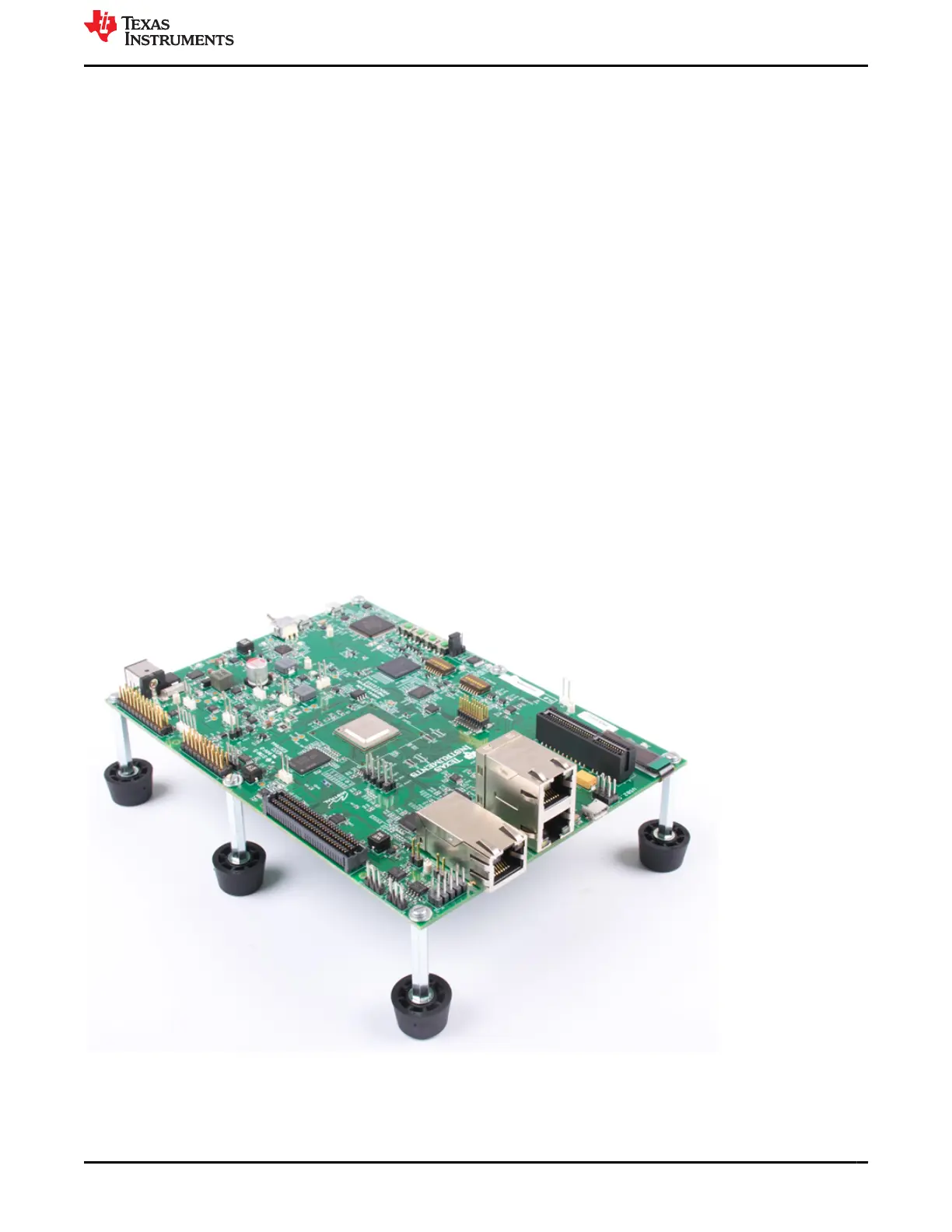
1 Introduction
The AM64x/AM243x GP EVM is a standalone test, development, and evaluation module (EVM) that lets
developers evaluate the AM64x/AM243x functionality and develop prototypes for a variety of applications. The
EVM implements either the Sitara
™
AM6442 MPU or the AM2434 MCU. Additional supporting components allow
the user to make use of the various device interfaces including Industrial Ethernet, standard Ethernet, PCIe,
Fast Serial Interface (FSI) and others to easily create prototypes. An on-board display makes use of AM64x/
AM243x serial peripheral interface (SPI) ports to provide the ability for local visual outputs in addition to the
various LED provided. On-board current measurement capabilities are available to monitor power consumption
for power-conscious applications. The supplied USB cable paired with embedded emulation logic allows for
emulation and debugging using standard development tools such as Code Composer Studio
™
software from TI.
www.ti.com
Trademarks
SPRUIX0C – FEBRUARY 2021 – REVISED JUNE 2021
Submit Document Feedback
AM64x/AM243x GP EVM User's Guide 3
Copyright © 2021 Texas Instruments Incorporated

 Loading...


