3.4.6 Test Automation
A Test automation header J38 is provided to allow an external controller to control the power on/off, boot modes,
reset functionality and current measurement to support automated testing. The test automation header includes
four GPIOs, two I2C interfaces. The basic controls as shown in Table 3-16.
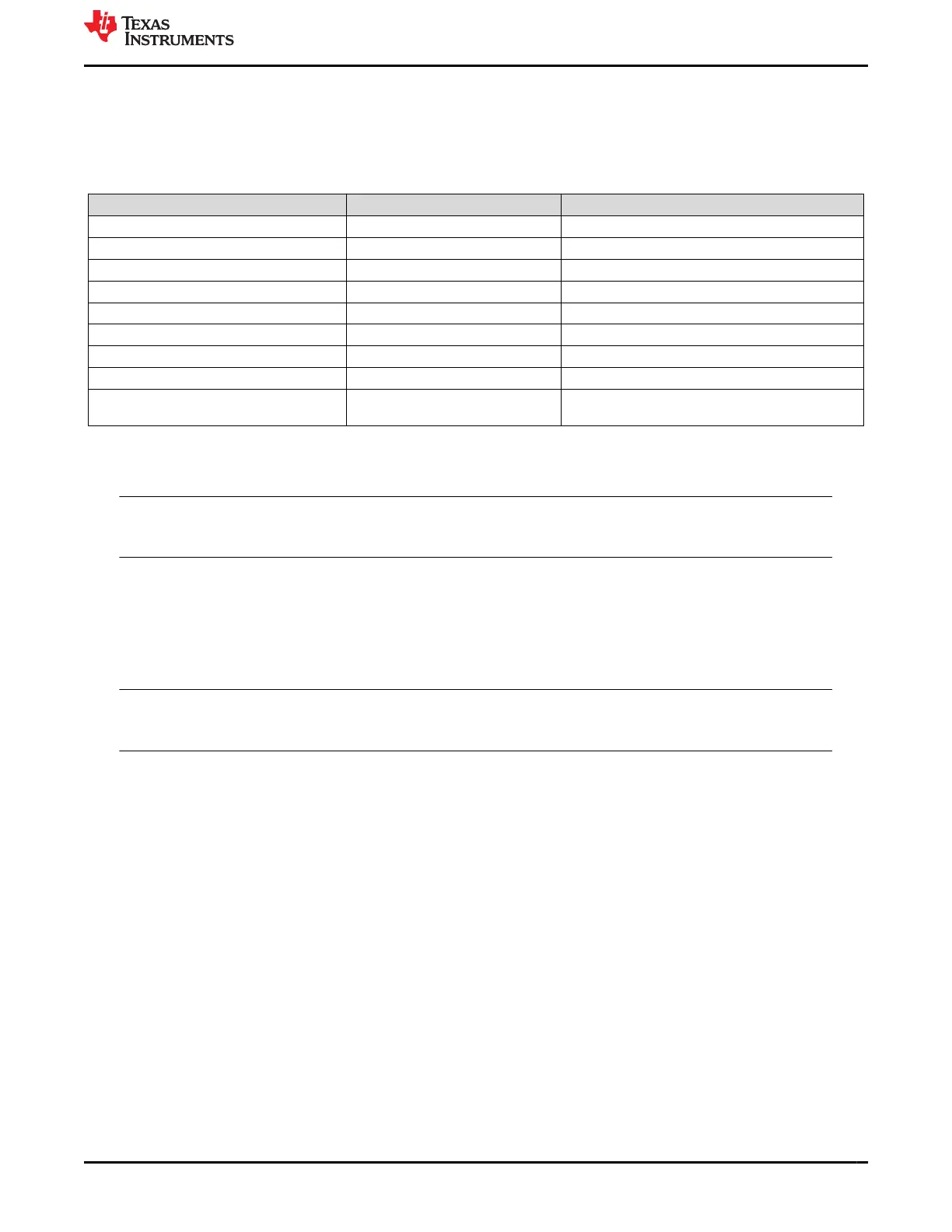
Table 3-16. List of Signals Routed to Test Automation Header
Signal Signal Type Function
POWER_DOWN GPIO Instructs the EVM to power down all circuits
POR GPIO Creates a PORz into the AM64x SoC
WARM_RESET GPIO Creates a RESETz into the AM64x SoC
GPIO1 GPIO GPIO for communication with AM64x SoC
GPIO2 GPIO Connected to I2C IO Expander
GPIO3 GPIO Used to Enable the BOOTMODE Buffer
GPIO4 GPIO Used to Reset the Boot mode IO Expander
I2C0 I2C Commnicates with Boot mode I2C buffer
I2C2 I2C Communicates with INA226 current measurement
devices
One of the I2C interface from Test automation header is connected to an I2C IO expander, which can drive the
Boot mode pins of the processor.
Note
The bootmode selection switches should be in the OFF condition and GPIO3 should be set to logic
low to enable this mode.
The other I2C interface is connected to the current measurement and temperature sensing devices present on
the I2C1 port of the SoC.
The Test Automation connector is used by Texas Instruments for control of software regression testing and
comparative power measurements. The connector is provided to allow customers to develop their own testing
and power measurements of customer applications.
Note
The power measurements are not a substitute for the AM64x/AM243x Power Estimation Tool and
should not be used for the design of power supply solutions.
Power measurements will vary based on silicon process and environment and measurements should only be
used for comparison with other measurements taken on the same EVM.
www.ti.com
System Description
SPRUIX0C – FEBRUARY 2021 – REVISED JUNE 2021
Submit Document Feedback
AM64x/AM243x GP EVM User's Guide 25
Copyright © 2021 Texas Instruments Incorporated

 Loading...


