3.4.20 FSI Interface
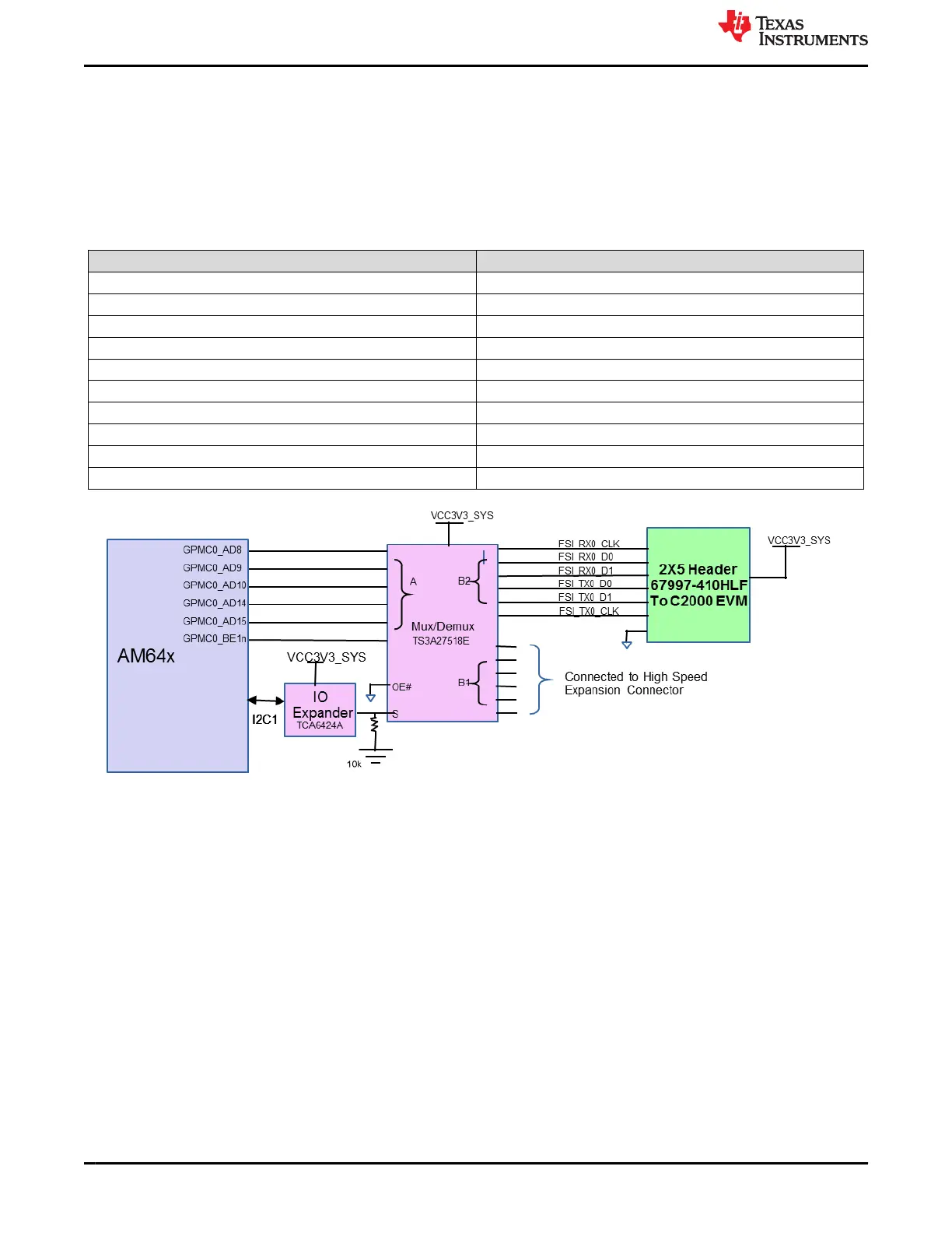
One FSI Interface (1Tx and 1Rx) from SoC is terminated on 2x5 header with part number 67997-410HLF from
Amphenol ICC (FCI) having connections which can be interfaced to C2000 EVM. FSI_TX0 signals and FSI_RX0
signals are connected to the mux so that they are available to both the FSI connector and the expansion
connector. The TS3A27518E mux-demux is used for this purpose and it is controlled by GPIO from IO Expander.
A logic low in Mux select pin connects port A and Port B1 whereas a logic high connects A port to B2 port. The
default state of mux drives the signals from A port to B1 port, which is connected to HSE connector.
Table 3-30. FSI (J5) Connector Pin-out
Pin No. Signal
1 FSI_TX0_CLK
2 FSI_RX0_CLK
3 DGND
4 DGND
5 FSI_TX0_D0
6 FSI_RX0_D0
7 FSI_TX0_D1
8 FSI_RX0_D1
9 DGND
10 VCC_3V3_SYS
Figure 3-31. AM64x/AM243x FSI Interface
System Description
www.ti.com
58 AM64x/AM243x GP EVM User's Guide SPRUIX0C – FEBRUARY 2021 – REVISED JUNE 2021
Submit Document Feedback
Copyright © 2021 Texas Instruments Incorporated

 Loading...


