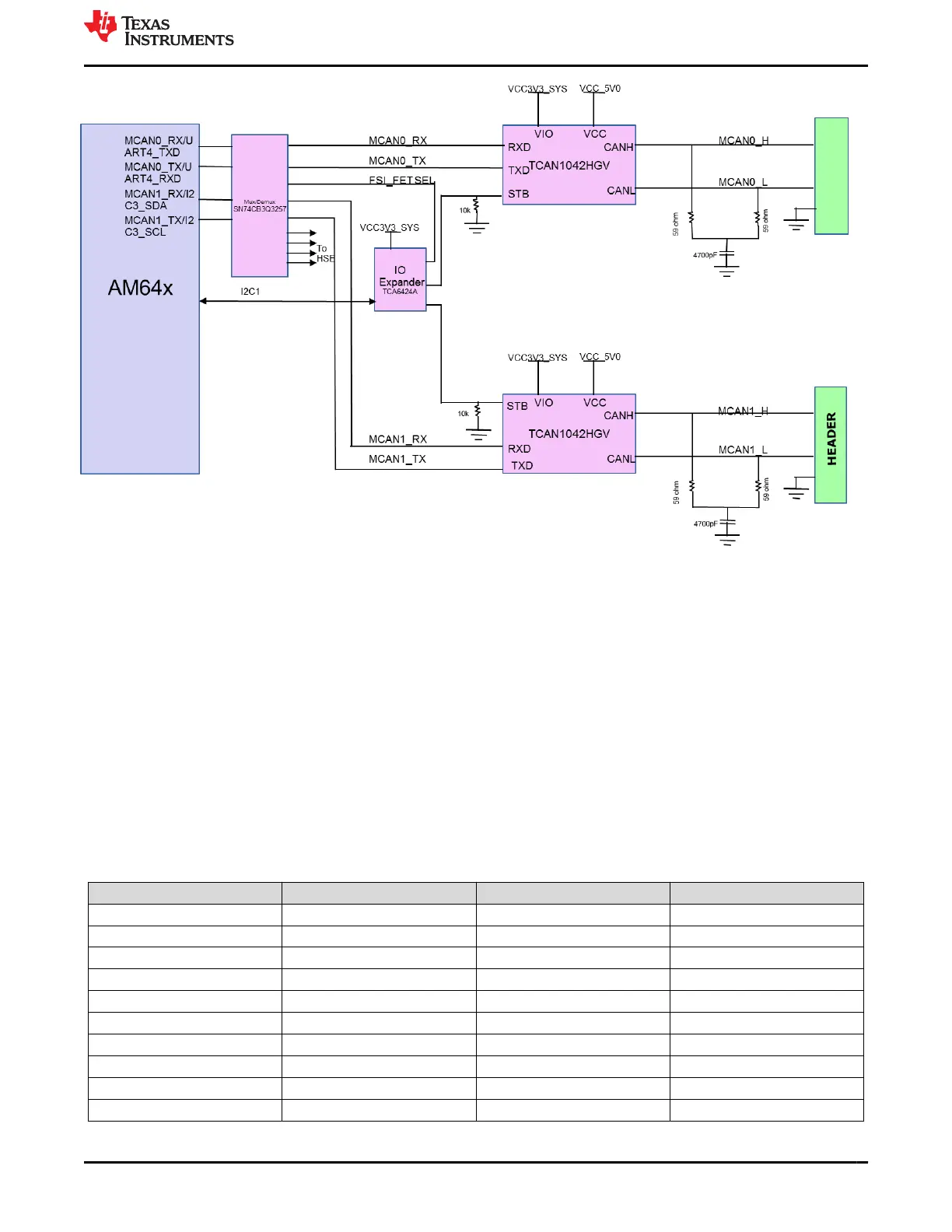
Figure 3-29. AM64x/AM243x CAN Interfaces
3.4.15 Interrupt
The GP EVM supports the following timer and interrupt options.
Three push button switches are available to provide reset for MCU_PORz and MCU_RESETz and
RESET_REQz. One push button switch is available for GPIO interrupt, which is connected to both main domain
and MCU domain GPIO pin.
Warm reset can also be applied through Test automation header or manual reset switches SW4 (SoC) and SW6
(MCU).
Power on reset input can be applied though switch SW7.
3.4.16 ADC Interface
A 20-pin connector J3 of part number TSW-110-07-S-D for connecting ADC signals of the AM64x/AM243x. The
connector includes ADC0_AIN0-7, VDDA_ADC connections and ground connections.
Table 3-26. ADC Connector (J3) Pin-out
Pin No. Signal Pin No. Signal
1 DGND 11 ADC0_AIN7
2 NC 12 DGND
3 ADC0_AIN6 13 DGND
4 VDDA_ADC 14 ADC0_AIN1
5 DGND 15 ADC0_AIN0
6 ADC0_AIN2 16 DGND
7 ADC0_AIN5 17 VDDA_ADC
8 DGND 18 ADC0_AIN3
9 DGND 19 NC
10 ADC0_AIN4 20 DGND
www.ti.com System Description
SPRUIX0C – FEBRUARY 2021 – REVISED JUNE 2021
Submit Document Feedback
AM64x/AM243x GP EVM User's Guide 55
Copyright © 2021 Texas Instruments Incorporated

 Loading...


