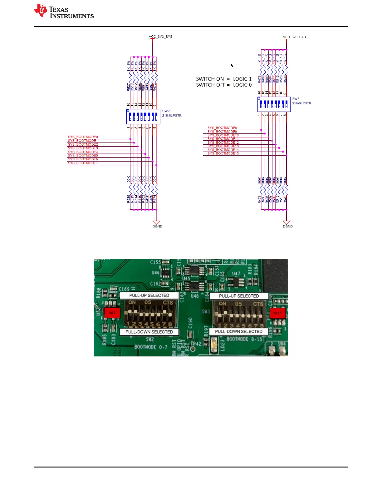
Figure 3-9. AM64x/AM243x GP EVM Schematic Excerpt, Boot Mode Selection Switches (SW2, SW3)
Figure 3-10. AM64x/AM243x GP EVP PCB, Boot Mode Selection Switches (SW2, SW3)
The BOOTMODE pins provide means to select the boot mode before the device is powered up. They are divided
into the following categories:
Note
The following bit pattern is reversed in the table from the switch order.
www.ti.com
System Description
SPRUIX0C – FEBRUARY 2021 – REVISED JUNE 2021
Submit Document Feedback
AM64x/AM243x GP EVM User's Guide 19
Copyright © 2021 Texas Instruments Incorporated

 Loading...


