3 System Description
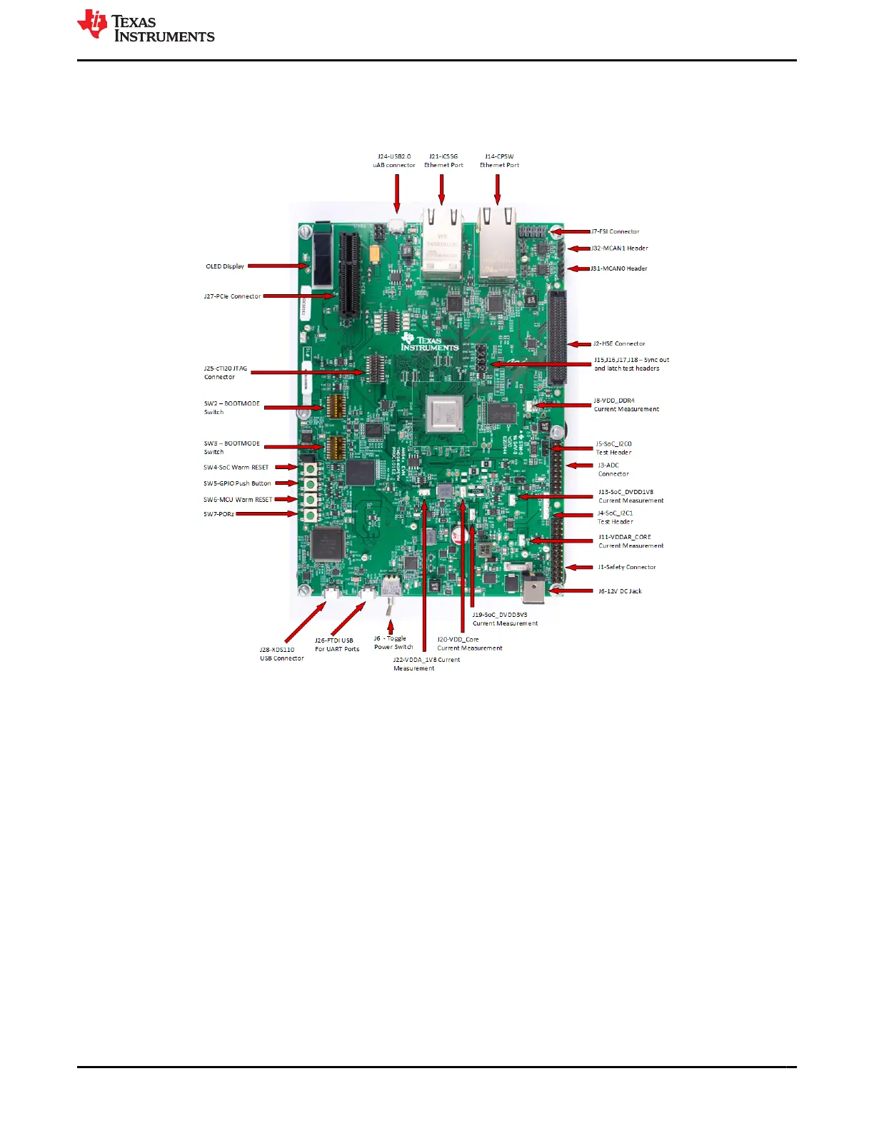
The following sections describe the AM64x/AM243x GP EVM design. Top-down and bottom-up views of the PCB
are provided in Figure 3-1 and Figure 3-2 for reference to major IC and connector component locations.
Figure 3-1. Top View of the AM64x/AM243x GP EVM Board
www.ti.com
System Description
SPRUIX0C – FEBRUARY 2021 – REVISED JUNE 2021
Submit Document Feedback
AM64x/AM243x GP EVM User's Guide 5
Copyright © 2021 Texas Instruments Incorporated

 Loading...


