Table 3-22 describes the jumper options used to select if the GP EVM will operate in Root Complex mode or in
End Point mode.
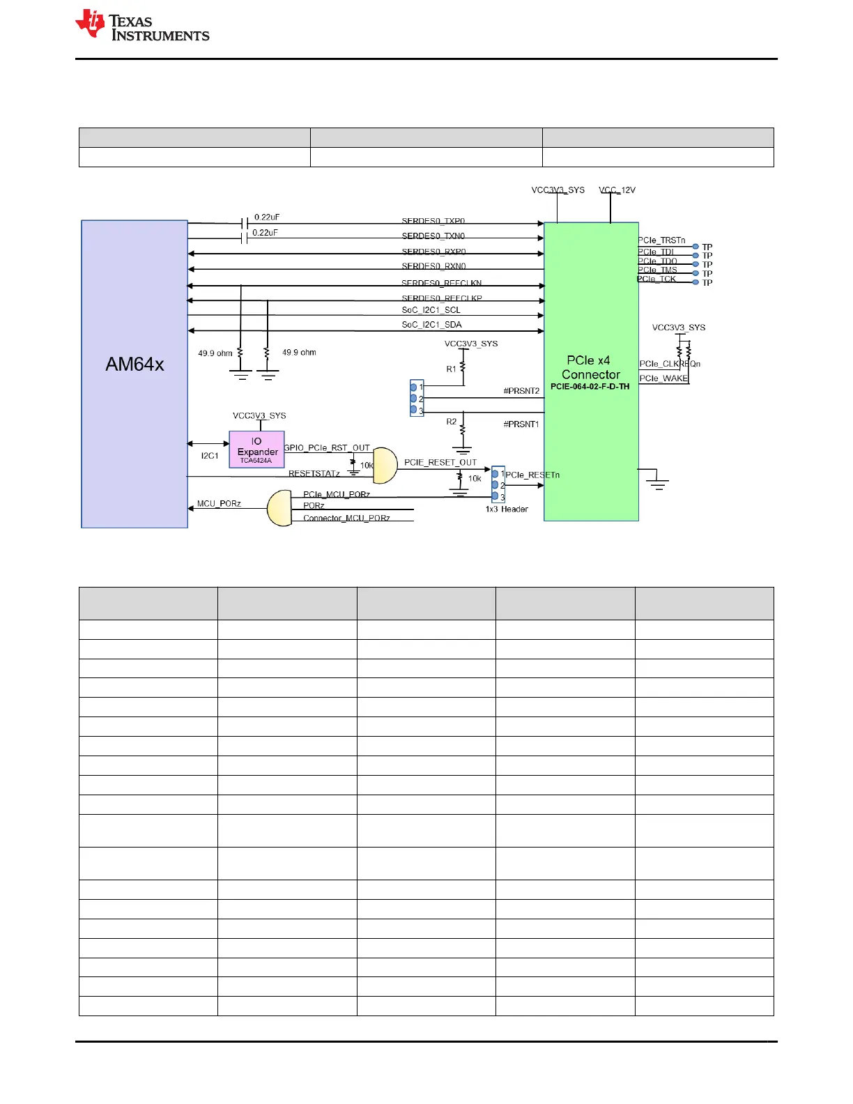
Table 3-22. PCIe Jumper Options to Enable Root Complex and Endpoint Mode
Root Complex End Point
1x3 header J34 and J35 Short 1 and 2 Short 2 and 3
Figure 3-25. AM64x/AM243x PCIe Interface
Table 3-23. PCIe Connector (J27) Pin-out
Pin No.
Side A of PCIe
Connector GP Board Signal
Side B of PCIe
Connector GP Board Signal
1 PRSNT1# J35.3 +12V VDD_12V
2 +12V VDD_12V +12V VDD_12V
3 +12V VDD_12V +12V VDD_12V
4 GND GROUND GND GROUND
5 JTAG2 TP SMCLK SoC_I2C1_CLK
6 JTAG3 TP SMDATA SoC_I2C1_SDA
7 JTAG4 TP GND GROUND
8 JTAG5 TP +3V3 VCC3V3_SYS
9 +3V3 VCC3V3_SYS JTAG1 TP
10 +3V3 VCC3V3_SYS 3V3 VAUX VCC3V3_SYS
11 PERST# J24.2 WAKE# Pulled up to
VCC3V3_SYS
12 GND GROUND RSVD4 Pulled up to
VCC3V3_SYS
13 REFCLK+ SERDES_REFCLK0P GND GROUND
14 REFCLK- SERDER_REFCLK0N PETp0 SERDES_TXP0
15 GND GROUND PETn0 SERDES_TXN0
16 PERp0 SERDES_RXP0 GND GND
17 PERn0 SERDES_RXN0 PRSNT2#_1 J35.2
18 GND GROUND GND GROUND
19 RSVD1 NC PETp1 NC
www.ti.com System Description
SPRUIX0C – FEBRUARY 2021 – REVISED JUNE 2021
Submit Document Feedback
AM64x/AM243x GP EVM User's Guide 45
Copyright © 2021 Texas Instruments Incorporated

 Loading...


