Analog-to-Digital Converter
ADC Control Register 3
ADC Control Register 3
ADCTRL3 @ 0x007118
ADCTRL3 @ 0x007118
(lab file:
(lab file:
Adc
Adc
.c)
.c)
Sampling Mode Select
Sampling Mode Select
0 = sequential sampling mode
0 = sequential sampling mode
1 = simultaneous sampling mode
1 = simultaneous sampling mode
ADC Clock
ADC Clock
Prescale
Prescale
ADCCLKPS3
ADCCLKPS3
ADCCLKPS2
ADCCLKPS2
ADCCLKPS1
ADCCLKPS1
ADCCLKPS0
ADCCLKPS0
SMODE_SEL
SMODE_SEL
4
4
2
2
0
0
1
1
3
3
ADCRFDN
ADCRFDN
ADCBGND
ADCBGND
ADCPWDN
ADCPWDN
7
7
5
5
6
6
15
15
-
-
8
8
reserved
ADC Reference
ADC Reference
Power Down
Power Down
0 = powered down
0 = powered down
1 = powered up
1 = powered up
ADC
ADC
Bandgap
Bandgap
Power Down
Power Down
0 = powered down
0 = powered down
1 = powered up
1 = powered up
ADC Power Down
ADC Power Down
(except
(except
Bandgap
Bandgap
& Ref.)
& Ref.)
0 = powered down
0 = powered down
1 = powered up
1 = powered up
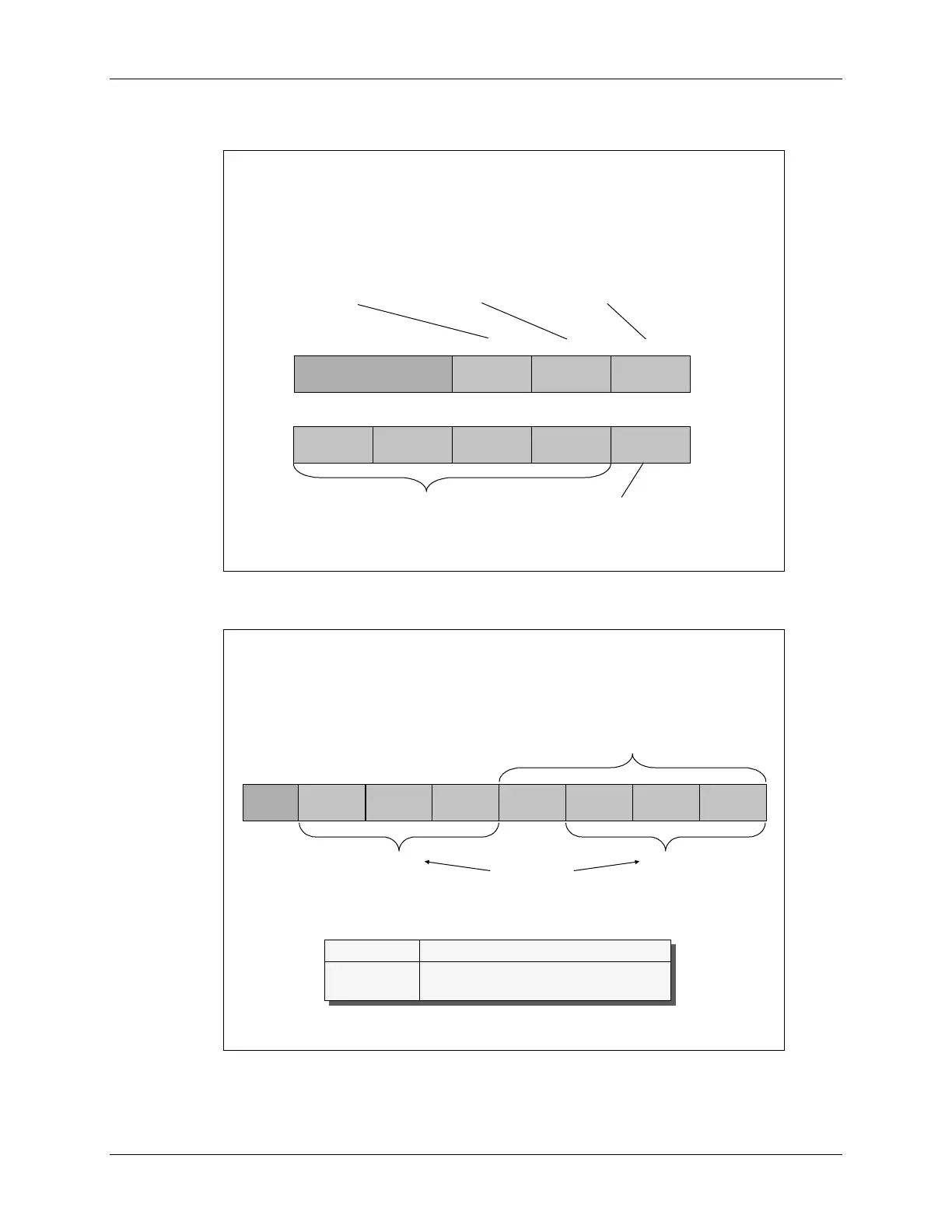
Maximum Conversion Channels Register
Maximum Conversion Channels Register
ADCMAXCONV @ 0x007102
ADCMAXCONV @ 0x007102
(lab file:
(lab file:
Adc
Adc
.c)
.c)
MAX_
MAX_
CONV 2_2
CONV 2_2
MAX_
MAX_
CONV 2_1
CONV 2_1
MAX_
MAX_
CONV 2_0
CONV 2_0
MAX_
MAX_
CONV 1_3
CONV 1_3
MAX_
MAX_
CONV 1_2
CONV 1_2
MAX_
MAX_
CONV 1_1
CONV 1_1
MAX_
MAX_
CONV 1_0
CONV 1_0
reserved
Cascaded Mode
Cascaded Mode
Dual Mode
Dual Mode
SEQ2
SEQ2
SEQ1
SEQ1
♦
♦
Bit fields define the maximum number of
Bit fields define the maximum number of
autoconversions
autoconversions
(binary+1)
(binary+1)
♦
♦
Autoconversion
Autoconversion
session always starts with the “initial state”
session always starts with the “initial state”
and continues sequentially until the “end state”, if allowed
and continues sequentially until the “end state”, if allowed
SEQ1 SEQ2 Cascade
SEQ1 SEQ2 Cascade
d
d
Initial state CONV00 CONV08 CONV00
Initial state CONV00 CONV08 CONV00
End state CONV07 CONV15 CONV15
End state CONV07 CONV15 CONV15
6 - 8 C28x - Analog-to-Digital Converter
 Loading...


