Lab 8: IQmath FIR Filter
Lab 8: IQmath FIR Filter
Objective
The objective of this lab is to apply the techniques discussed in module 8 and to become familiar
with IQmath programming. In the previous lab, General-Purpose Timer 1 and Compare 1 from
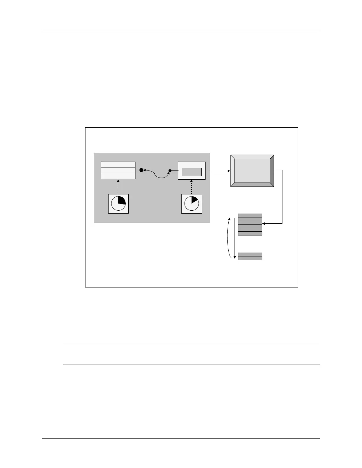
Event Manager A (EVA) were setup to generate a 2 kHz, 25% duty cycle symmetric PWM
waveform. The waveform was then sampled with the on-chip analog-to-digital converter. In this
lab the sampled waveform will be passed through an IQmath FIR filter and displayed using the
graphing feature of Code Composer Studio.
Lab 8:
Lab 8:
IQmath
IQmath
FIR Filter
FIR Filter
CPU copies
result to
buffer during
ADC ISR
ADC
RESULT0
GP Timer 2
GP Timer 2 triggers
ADC SOC every
20 µs (50 kHz)
connector
wire
Compare 1
PWM Circuits
Output Logic
GP Timer 1
Event Manager
ADCINA0
...
data
memory
p
o
i
n
t
e
r
r
e
w
i
n
d
Display
Display
using CCS
using CCS
IQmath
IQmath
FIR Filter
FIR Filter
Procedure
Project File
Note: LAB8 files have been provided as a starting point for the lab and need to be
completed. DO NOT copy files from a previous lab.
1. A project named Lab8.pjt has been created for this lab. Open the project by clicking
on Project Open… and look in C:\C28x\LABS\LAB8. All Build Options
have been configured like the previous lab. The files used in this lab are:
8 - 36 C28x - Numerical Concepts & IQmath
 Loading...


