Lab 7: Event Manager
Lab 7: Event Manager
Objective
The objective of this lab is to apply the techniques discussed in module 7 and become familiar
with the programming and operation of the Event Manager and its interrupts. General-Purpose
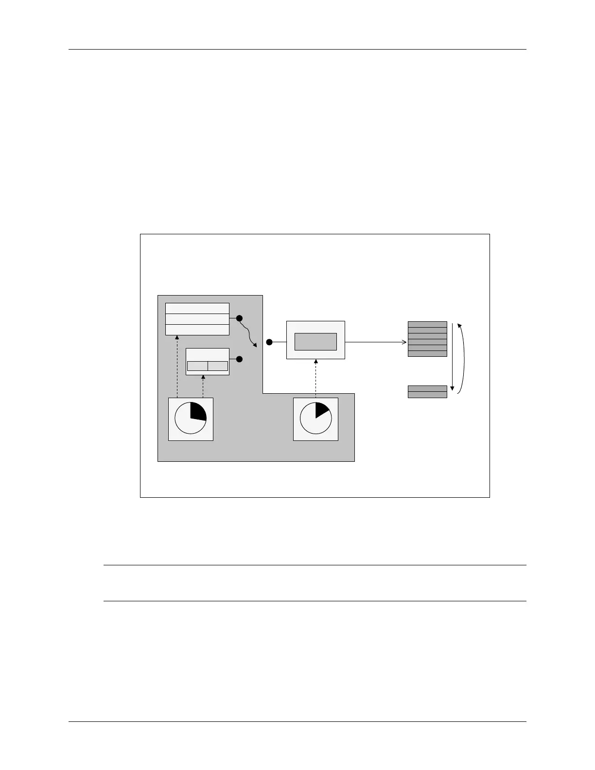
Timer 1 and Compare 1 will be setup to generate a 2 kHz, 25% duty cycle symmetric PWM
waveform. The waveform will then be sampled with the on-chip analog-to-digital converter and
displayed using the graphing feature of Code Composer Studio. Next, Capture Unit 1 will be
setup to detect the rising and falling edges of the waveform. This information will be used to
determine the width of the pulse and duty cycle of the waveform. The results of this step will be
viewed numerically in a memory window.
Lab 7: Event Manager
Lab 7: Event Manager
(EVA)
(EVA)
ADC
RESULT0
...
data
memory
p
o
i
n
t
e
r
r
e
w
i
n
d
CPU copies
result to
buffer during
ADC ISR
GP Timer 2
GP Timer 2 triggers
ADC SOC every
20 µs (50 kHz)
connector
wire
Compare 1
PWM Circuits
Output Logic
Capture 1
FIFO FIFO
GP Timer 1
Event Manager
ADC-
INA0
Procedure
Project File
Note: LAB7 files have been provided as a starting point for the lab and need to be
completed. DO NOT copy files from a previous lab.
1. A project named Lab7.pjt has been created for this lab. Open the project by clicking
on
Project Open… and look in C:\C28x\LABS\LAB7. All Build Options
have been configured like the previous lab. The files used in this lab are:
7 - 36 C28x - Event Manager
 Loading...


