Lab 6: Analog-to-Digital Converter
Lab 6: Analog-to-Digital Converter
Objective
The objective of this lab is to apply the techniques discussed in module 6 and to become familiar
with the programming and operation of the on-chip analog-to-digital converter. The DSP will be
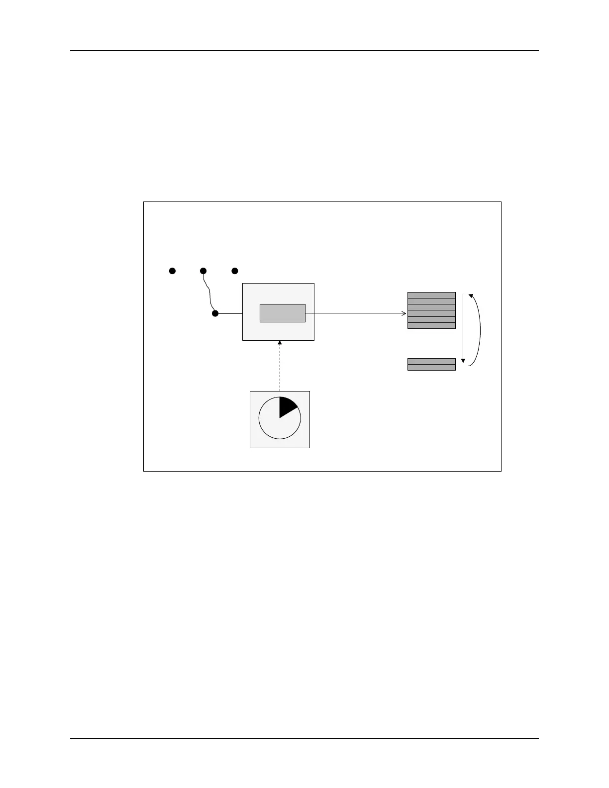
setup to sample a single ADC input channel at a prescribed sampling rate and store the
conversion result in a buffer in the DSP memory. This buffer will operate in a circular fashion,
such that new conversion data continuously overwrites older results in the buffer.
Lab 6: Analog
Lab 6: Analog
-
-
to
to
-
-
Digital Converter
Digital Converter
(1 of 2)
(1 of 2)
Sampling
Sampling
ADC
ADC
ADCINA0
ADCINA0
RESULT0
RESULT0
...
...
data
data
memory
memory
p
o
i
n
t
e
r
r
e
w
i
n
d
p
o
i
n
t
e
r
r
e
w
i
n
d
CPU copies result
CPU copies result
to buffer during
to buffer during
ADC ISR
ADC ISR
GP Timer 2
GP Timer 2
GP Timer 2 triggers
GP Timer 2 triggers
ADC SOC every
ADC SOC every
20
20
µ
µ
s (50 kHz)
s (50 kHz)
GND
GND
+3.3 V
+3.3 V
GPIOA1
GPIOA1
connector
connector
wire
wire
Recall that there are three basic ways to initiate an ADC start of conversion (SOC):
1. Using software
a. SOC_SEQ1/SOC_SEQ2 bit in ADCTRL2 causes an SOC upon completion of the current
conversion (if the ADC is currently idle, an SOC occurs immediately)
2. Automatically triggered on user selectable event manager conditions
a. GP Timer 1 or 2 (EVA); 3 or 4 (EVB) underflow (e.g. timer count = 0)
b. GP Timer 1 or 2 (EVA); 3 or 4 (EVB) period match
c. GP Timer 1 or 2 (EVA); 3 or 4 (EVB) compare match
3. Externally triggered using a pin
a. ADCSOC pin
b. CAP3 pin - EVA; CAP6 pin - EVB (capture unit #3 / capture unit #6 edge detection)
One or more of these methods may be applicable to a particular application. In this lab, we will
be using the ADC for data acquisition. Therefore, one of the GP timers (GP Timer 2) will be
configured to automatically trigger an SOC at the desired sampling rate (SOC method 2b above).
The ADC end-of-conversion interrupt will be used to prompt the CPU to copy the results of the
ADC conversion into a results buffer in memory. This buffer pointer will be managed in a
circular fashion, such that new conversion results will continuously overwrite older conversion
results in the buffer. In order to generate an interesting input signal, the code also alternately
C28x - Analog-to-Digital Converter 6 - 13
 Loading...


