Lab 6: Analog-to-Digital Converter
toggles a GPIO pin (GPIOA1) high and low in the ADC interrupt service routine. The ADC ISR
will also toggle LED DS2 on the eZdsp™ as a visual indication that the ISR is running. This pin
will be connected to the ADC input pin, and sampled. After taking some data, Code Composer
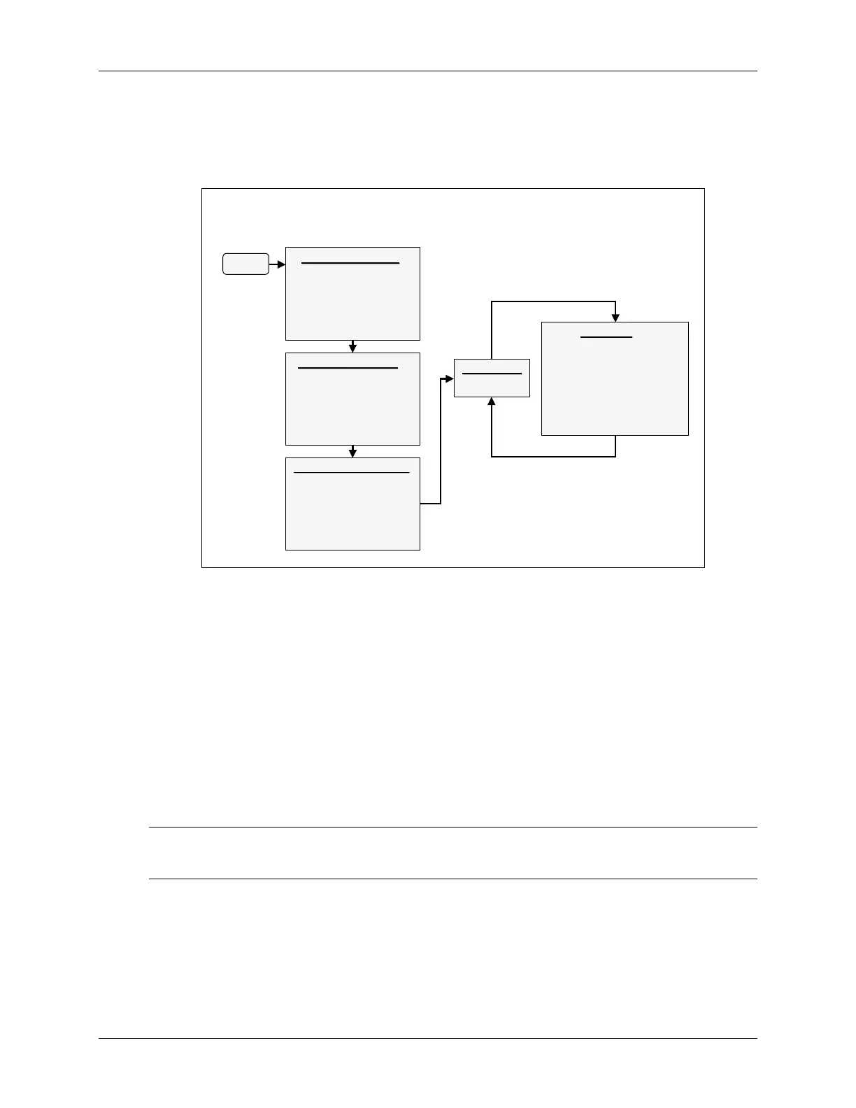
Studio will be used to plot the results. A flow chart of the code is shown in the following slide.
Lab 6: Code Flow Diagram
Lab 6: Code Flow Diagram
(2 of 2)
(2 of 2)
Start
Start
CPU Initialization
CPU Initialization
•
•
watchdog disable
watchdog disable
•
•
SCSR register
SCSR register
•
•
software stack
software stack
•
•
core interrupts
core interrupts
•
•
shared pins
shared pins
•
•
GPIO setup
GPIO setup
ADC Initialization
ADC Initialization
•
•
convert channel A0 on
convert channel A0 on
Timer2 period match
Timer2 period match
•
•
send interrupt on
send interrupt on
every conversion
every conversion
•
•
setup a results buffer
setup a results buffer
in memory
in memory
Timer 2 Initialization
Timer 2 Initialization
•
•
clear counter
clear counter
•
•
set period register
set period register
•
•
set to trigger ADC on
set to trigger ADC on
period match
period match
•
•
set the clock
set the clock
prescaler
prescaler
•
•
enable the timer
enable the timer
Main Loop
Main Loop
loop: B loop
loop: B loop
ADC ISR
ADC ISR
•
•
context save
context save
•
•
read the ADC result
read the ADC result
•
•
write to result buffer
write to result buffer
•
•
adjust the buffer pointer
adjust the buffer pointer
•
•
toggle the GPIO pin
toggle the GPIO pin
•
•
context restore
context restore
•
•
re
re
-
-
enable interrupts
enable interrupts
•
•
return
return
ADC interrupt
ADC interrupt
return
return
Notes
• Program performs conversion on ADC channel A0 (ADCINA0 pin)
• General Purpose Timer 2 is used to auto-trigger the conversions at a 50kHz sampling rate
• Data is continuously stored in a circular buffer
• GPIOA1 pin is also toggled in the ADC ISR
• ADC ISR will also toggle the eZdsp™ LED DS2 as a visual indication that it is running
Procedure
Project File
Note: LAB6 files have been provided as a starting point for the lab and need to be
completed. DO NOT copy files from a previous lab.
1. A project named Lab6.pjt has been created for this lab. Open the project by clicking
on Project Open… and look in C:\C28x\LABS\LAB6. All Build Options
have been configured like the previous lab. The files used in this lab are:
6 - 14 C28x - Analog-to-Digital Converter
 Loading...


