EALLOW Protected Registers
EALLOW Protected Registers
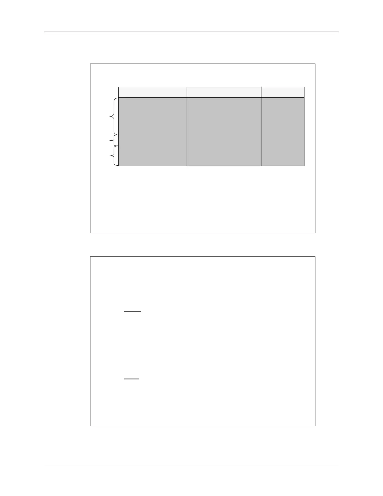
EALLOW Protected Registers
EALLOW Protected Registers
Register Name
Register Name
Address Range
Address Range
size (x16)
size (x16)
Device Emulation
Device Emulation
0x00 0880
0x00 0880
–
–
0x00 09FF 384
0x00 09FF 384
FLASH
FLASH
0x00 0A00
0x00 0A00
–
–
0x00 0ADF
0x00 0ADF
96
96
Code Security Module
Code Security Module
0x00 0AE0
0x00 0AE0
–
–
0x00 0AEF
0x00 0AEF
16
16
PIE Vector Table
PIE Vector Table
0x00 0D00
0x00 0D00
–
–
0x00 0DFF
0x00 0DFF
256
256
eCAN
eCAN
0x00 6000
0x00 6000
–
–
0x00 60FF 256 (128x32)
0x00 60FF 256 (128x32)
System Control
System Control
0x00 7010
0x00 7010
–
–
0x00 702F
0x00 702F
32
32
GPIO
GPIO
Mux
Mux
0x00 70C0
0x00 70C0
–
–
0x00 70DF
0x00 70DF
32
32
PF0
PF0
PF1
PF1
PF2
PF2
(also protected by CSM)
(also protected by CSM)
while(1) // dummy loop
while(1) // dummy loop
-
-
wait for an interrupt
wait for an interrupt
{
{
asm
asm
("
("
EALLOW
EALLOW
");
");
// enable EALLOW protected register access
// enable EALLOW protected register access
SysCtrlRegs
SysCtrlRegs
.WDKEY=0x55; // watchdog enabled for reset on next 0xAA wri
.WDKEY=0x55; // watchdog enabled for reset on next 0xAA wri
te
te
asm
asm
("
("
EDIS
EDIS
"); // disable EALLOW protected regi
"); // disable EALLOW protected regi
ster access
ster access
}
}
Note: “
Note: “
SysCtrlRegs
SysCtrlRegs
.WDKEY=0xAA” is located in an interrupt service routine
.WDKEY=0xAA” is located in an interrupt service routine
Lab 5: Procedure
Lab 5: Procedure
-
-
System Initialization
System Initialization
LAB5 files have been provided as a starting point
LAB5 files have been provided as a starting point
Modify LAB5 files to:
Modify LAB5 files to:
Part 1
Part 1
Disable the watchdog
Disable the watchdog
–
–
clear WD flag, disable watchdog, WD
clear WD flag, disable watchdog, WD
prescale
prescale
= 1
= 1
Setup the clock module
Setup the clock module
–
–
PLL = x5, HISPCP = /1, LOSPCP = /4,
PLL = x5, HISPCP = /1, LOSPCP = /4,
low
low
-
-
power modes to default values, enable all module clocks
power modes to default values, enable all module clocks
Setup control register
Setup control register
–
–
DO NOT clear WD OVERRIDE bit, WD
DO NOT clear WD OVERRIDE bit, WD
generate a DSP reset
generate a DSP reset
Setup shared I/O pins
Setup shared I/O pins
–
–
set all GPIO pins to GPIO function (e.g. a
set all GPIO pins to GPIO function (e.g. a
"0" setting for GPIO function, and a
"0" setting for GPIO function, and a
“
“
1
1
”
”
setting for peripheral
setting for peripheral
function)
function)
Part 2
Part 2
Initialize peripheral interrupt expansion (PIE) vectors
Initialize peripheral interrupt expansion (PIE) vectors
Build, debug, and test your code using Code
Build, debug, and test your code using Code
Composer Studio
Composer Studio
5 - 14 C28x - System Initialization
 Loading...


