Core Interrupt Lines
Reset - Bootloader
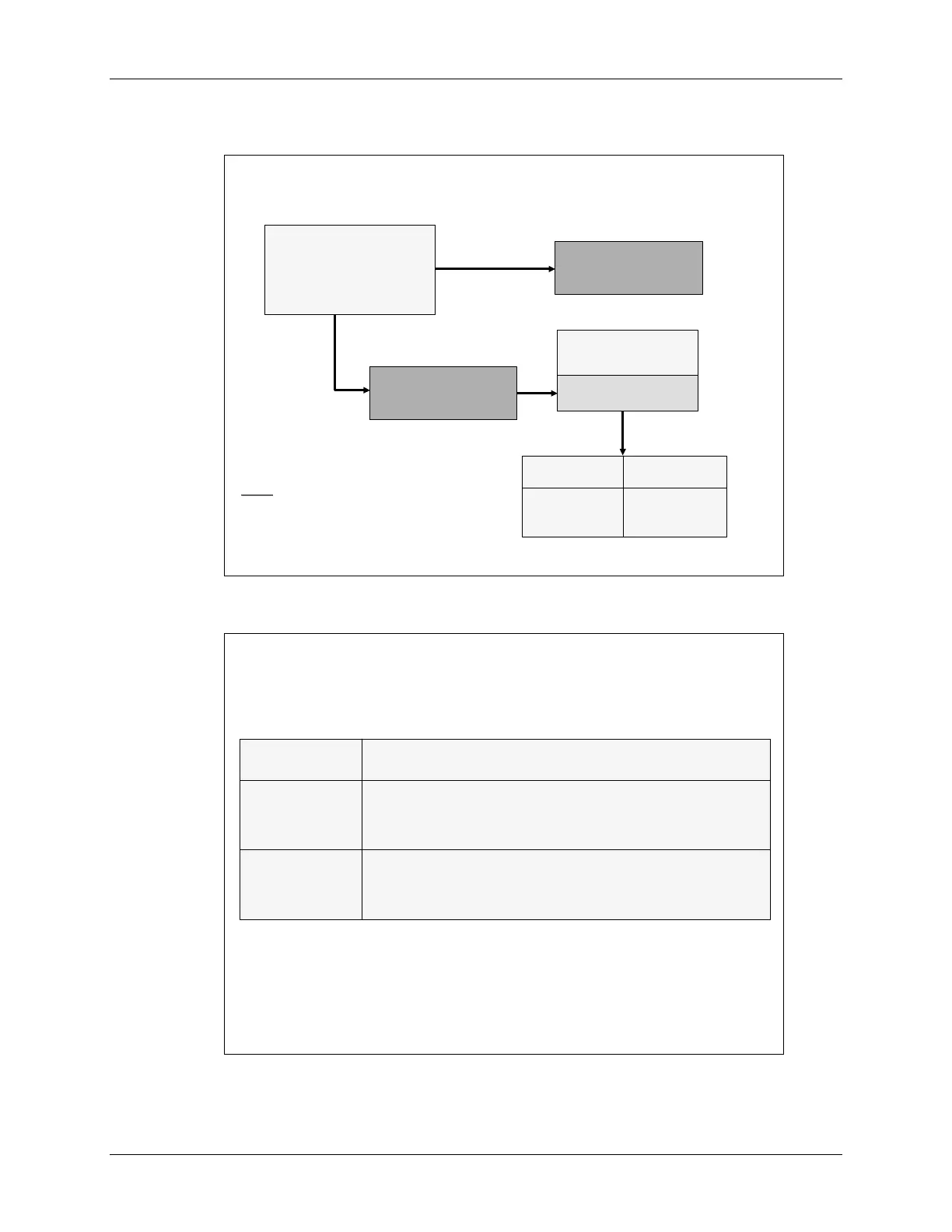
Reset
Reset
–
–
Bootloader
Bootloader
Reset
Reset
OBJMODE=0 AMODE=0
OBJMODE=0 AMODE=0
ENPIE=0 VMAP=1
ENPIE=0 VMAP=1
Boot determined by
Boot determined by
state of GPIO pins
state of GPIO pins
Reset vector fetched
Reset vector fetched
from boot ROM
from boot ROM
0x3F FFC0
0x3F FFC0
XMPNMC=1
XMPNMC=1
(microprocessor mode)
(microprocessor mode)
Reset vector fetched
Reset vector fetched
from XINTF zone 7
from XINTF zone 7
0x3F FFC0
0x3F FFC0
XMPNMC=0
XMPNMC=0
(microcomputer mode)
(microcomputer mode)
Execution
Execution
Bootloading
Bootloading
Entry Point
Entry Point
Routines
Routines
FLASH
FLASH
SPI
SPI
H0 SARAM
H0 SARAM
SCI
SCI
-
-
A
A
OTP
OTP
Parallel load
Parallel load
Notes:
Notes:
F2810 XMPNMC tied low internal to device
F2810 XMPNMC tied low internal to device
XMPNMC refers to input signal
XMPNMC refers to input signal
MP/MC is status bit in XINTFCNF2 register
MP/MC is status bit in XINTFCNF2 register
XMPNMC only sampled at reset
XMPNMC only sampled at reset
Bootloader
Bootloader
sets
sets
OBJMODE = 1
OBJMODE = 1
AMODE = 0
AMODE = 0
Bootloader
Bootloader
Options
Options
GPIO pins
GPIO pins
F4 F12 F3 F2
F4 F12 F3 F2
1 x x x jump to
1 x x x jump to
FLASH
FLASH
address 0x3F 7FF6 *
address 0x3F 7FF6 *
0 0 1 0 jump to
0 0 1 0 jump to
H0 SARAM
H0 SARAM
address 0x3F 8000 *
address 0x3F 8000 *
0 0 0 1 jump to
0 0 0 1 jump to
OTP
OTP
address 0x3D 7800 *
address 0x3D 7800 *
0 1 x x
0 1 x x
bootload
bootload
external EEPROM to on
external EEPROM to on
-
-
chip memory via
chip memory via
SPI
SPI
port
port
0 0 1 1
0 0 1 1
bootload
bootload
code to on
code to on
-
-
chip memory via
chip memory via
SCI
SCI
-
-
A
A
port
port
0 0 0 0
0 0 0 0
bootload
bootload
code to on
code to on
-
-
chip memory via
chip memory via
GPIO port B
GPIO port B
(parallel)
(parallel)
* Boot ROM software configures the device for C28x mode before j
* Boot ROM software configures the device for C28x mode before j
ump
ump
C28x - Reset and Interrupts 4 - 5
 Loading...


