General-Purpose Timers
PWM Outputs and Interrupts
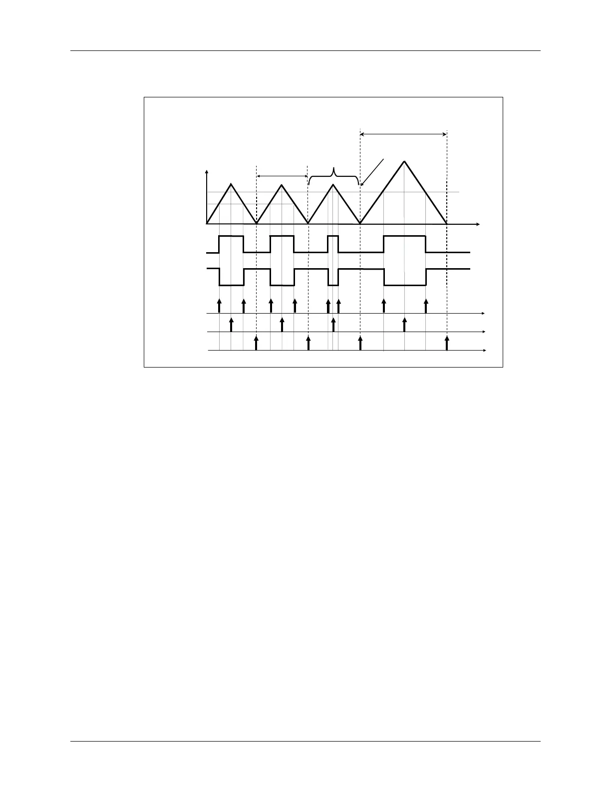
Generated Outputs and Interrupts
Generated Outputs and Interrupts
TxCMP
TxCMP
/
/
TxPWM
TxPWM
(active high)
(active high)
Compare
Compare
Ints
Ints
Period
Period
Ints
Ints
Underflow
Underflow
Ints
Ints
PWM period #2
PWM period #2
Timer Counter
Timer Counter
Value
Value
PWM period #1
PWM period #1
Comp1
Comp1
Comp2
Comp2
CPU Changes
CPU Changes
Period Reg. Buffer
Period Reg. Buffer
anytime here
anytime here
New Period is
New Period is
Auto
Auto
-
-
loaded on
loaded on
Underflow here
Underflow here
TxCMP
TxCMP
/
/
TxPWM
TxPWM
(active low)
(active low)
GP Timer Registers
As was the case with the period register, buffering is present for each timer compare register.
Software writes a value to the compare register buffer, from which the TxCMPR register is
automatically loaded on one of three user selected events:
1. timer underflow (TxCNT = 0)
2. timer underflow or period match
3. immediately
The event selection is made using bits 2 and 3 of the TxCON register, and allows for on-the-fly
compare value changes. Note that the compare register buffer is static in that if no change in the
current compare value is desired, one is not required to write the same value to the buffer on
successive timer cycles.
Each GP Timer unit has its own Symmetric/Asymmetric PWM Waveform Generator, which as its
name implies, is capable of generating two types of PWM. The waveform generator uses the
timer compare signal as an input, and outputs a PWM signal to the Output Logic Unit. The
output logic lets the user select the polarity of the TTL signal on the TxPWM/TxCMP pin (e.g.
active high or low) or alternately force the pin either high or low. The selection is made using
bits 0-1, and 2-3 of the GPTCONA register for timers 1 and 2 respectively (EVA), and bits 0-1,
and 2-3 of the GPTCONB register for timers 3 and 4 respectively (EVB).
7 - 12 C28x - Event Manager
 Loading...


