Lab 6: Analog-to-Digital Converter
Run the Code
10. In Main_6.c place the cursor in the “main loop” section, right click on the
mouse key and select Run To Cursor.
11. Open a memory window to view some of the contents of the ADC results buffer. The
address label for the ADC results buffer is AdcBuf.
Note: For the next set of steps “VREFLO” must be connected to “GND”. Using a connector
wire provided, connect “VREFLO” (pin # P9-18) to “GND” (pin # P9-17). Exercise
care when connecting any wires, as the power to the eZdsp™ is on, and we do not
want to damage the eZdsp™! Details of pin assignments can be found in Appendix A.
12. Using another connector wire provided, connect the ADCINA0 (pin # P9-2) to “GND”
(pin # P9-1) on the eZdsp™. Then run the code again, and halt it after a few seconds.
Verify that the ADC results buffer contains the expected value of 0x0000.
13. Adjust the connector wire to connect the ADCINA0 (pin # P9-2) to “+3.3V” (pin # P2-
45) on the eZdsp™. Then run the code again, and halt it after a few seconds. Verify that
the ADC results buffer contains the expected value of 0x0FFF.
14. Adjust the connector wire to connect the ADCINA0 (pin # P9-2) to IOPA1 (pin # P8-10)
on the eZdsp™. Then run the code again, and halt it after a few seconds. Examine the
contents of the ADC results buffer (the contents should be alternating 0x0000 and
0x0FFF values). Are the contents what you expected?
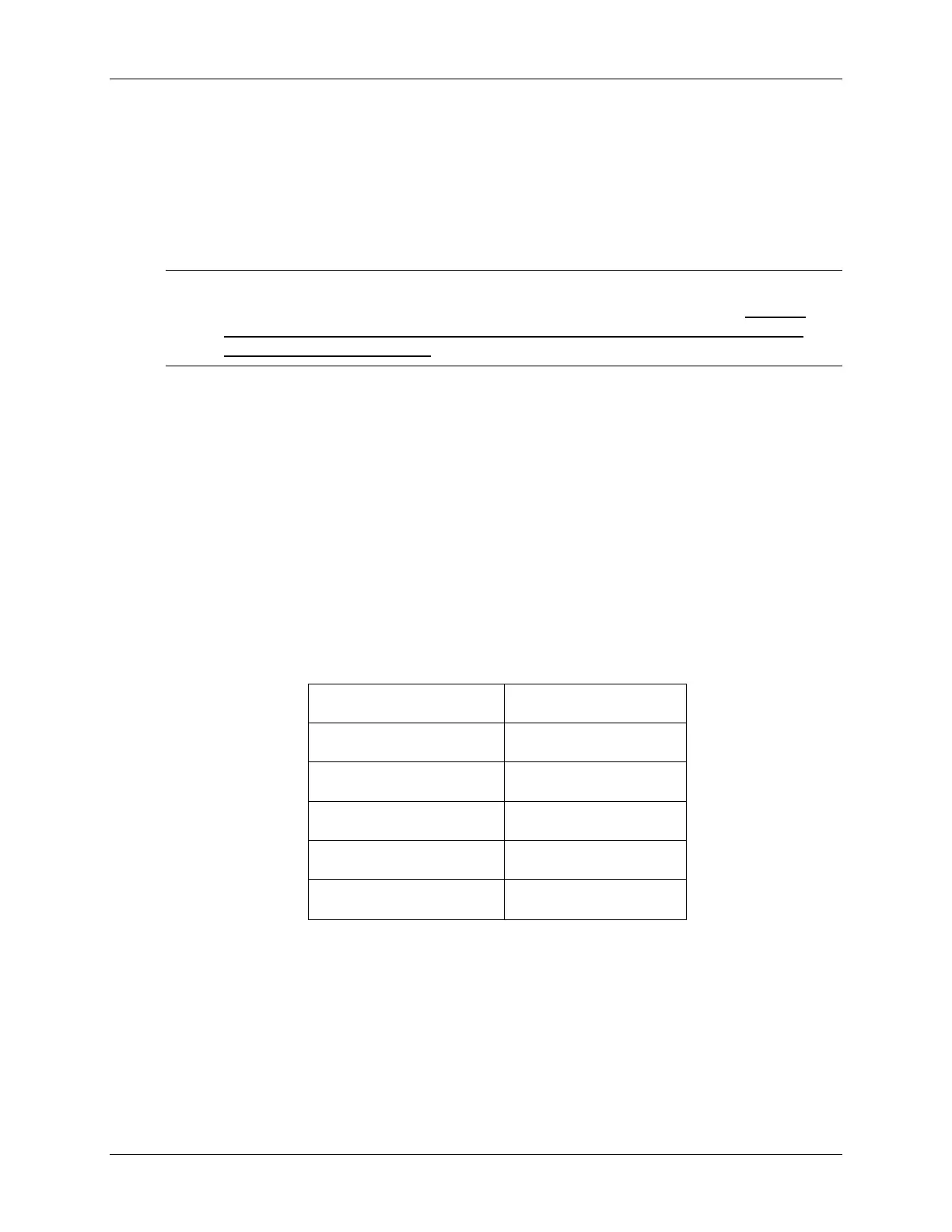
15. Open and setup a graph to plot a 50-point window of the ADC results buffer.
Click: View Graph Time/Frequency… and set the following values:
Start Address AdcBuf
Acquisition Buffer Size 50
Display Data Size 50
DSP Data Type 16-bit unsigned integer
Sampling Rate (Hz) 50000
Time Display Unit
µs
Select OK to save the graph options.
16. Recall that the code toggled the IOPA1 pin alternately high and low. (Also, the ADC
ISR is toggling the LED DS2 on the eZdsp™ as a visual indication that the ISR is
running). If you had an oscilloscope available to display IOPA1, you would expect to see
a square-wave. Why does Code Composer Studio plot resemble a saw-tooth wave?
What is the signal processing term for what is happening here?
6 - 16 C28x - Analog-to-Digital Converter
 Loading...


