General-Purpose Timers
General
General
-
-
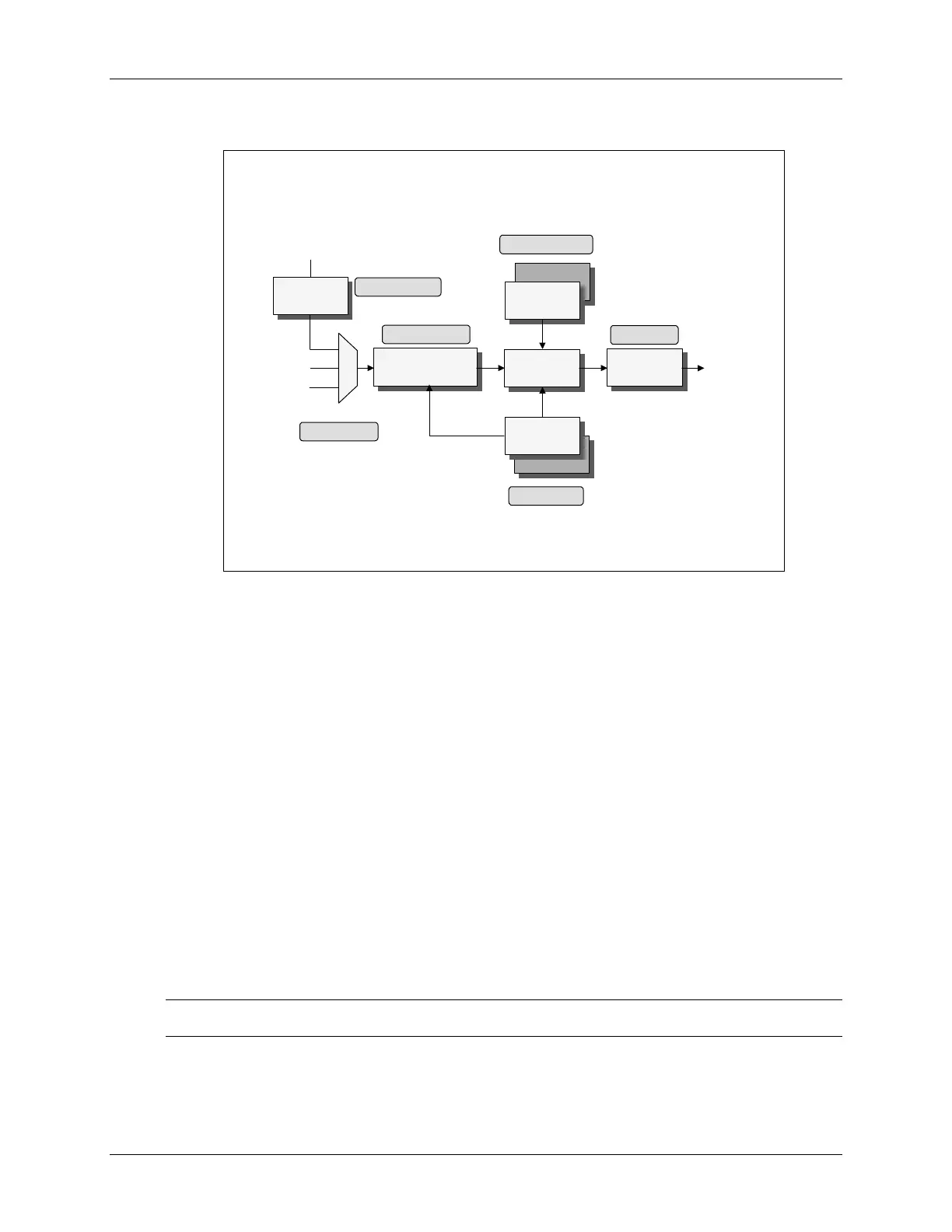
Purpose Timer Block Diagram
Purpose Timer Block Diagram
(EVA)
(EVA)
16
16
-
-
Bit Timer
Bit Timer
Counter
Counter
TxCMPR
TxCMPR
. 15
. 15
-
-
0
0
GPTCONA
GPTCONATxCNT
TxCNT
. 15
. 15
-
-
0
0
Compare
Compare
Logic
Logic
Clock
Clock
Prescaler
Prescaler
Output
Output
Logic
Logic
TPS 2
TPS 2
-
-
0
0
TxCON
TxCON
. 10
. 10
-
-
8
8
Period
Period
Register
Register
Shadowed
Shadowed
Compare
Compare
Register
Register
Shadowed
Shadowed
TxPR
TxPR
. 15
. 15
-
-
0
0
External
External
Internal
Internal
(HSPCLK)
(HSPCLK)
TCLKS 1
TCLKS 1
-
-
0
0
TxCON
TxCON
. 5
. 5
-
-
4
4
TxPWM
TxPWM
_
_
TxCMP
TxCMP
Note: x = 1 or 2
Note: x = 1 or 2
QEP
QEP
M
M
U
U
X
X
The TxPR period register holds the user specified counting period. TxPR is automatically loaded
from the period register buffer on a counter underflow, which is defined as TxCNT=0. This
allows for on-the-fly timer period changes. Note that the period register buffer is static in that if
no change in the current period value is desired, one is not required to write the same value to the
buffer on successive timer cycles.
The clocking signal for each GP Timer can be individually selected as either the internal CPU
clock, or the external TCLKINA/B pin. In addition, the QEP outputs can be selected for clocking
GP Timers. The external TDIRA/B pin is used to determine the counting direction only when the
timer is in the directional-up/down counting mode. The prescale counter is used to divide the
clocking signal down to the desired frequency, when necessary.
Each GP Timer has its own set of interrupts, all of which are individually maskable:
1. TxPINT - period match interrupt. Flag is set when the timer counter matches the value in
the timer period register.
2. TxUFINT - underflow interrupt. Flag is set when the timer counter becomes zero.
3. TxOFINT - overflow interrupt. Flag is set when the timer counter matches 0FFFFh.
Note: Maximum frequency for External or QEP is CLKIN/4
C28x - Event Manager 7 - 9
 Loading...


