Lab 10: Programming the Flash
Main_10.c Labcfg.cmd
Lab.cdb DSP281x_Headers_BIOS.cmd
User_10.cmd CodeStartBranch.asm
SysCtrl.c Gpio.c
DSP281x_GlobalVariableDefs.c PieCtrl_10.c
DefaultIsr_9_10.c Adc.c
Ev_7_8_9_10.c Filter.c
Link Initialized Sections to Flash
Initialized sections, such as code and constants, must contain valid values at device power-up.
For a stand-alone embedded system with the F2812 device, these initialized sections must be
linked to the on-chip flash memory. Note that a stand-alone embedded system must operate
without an emulator or debugger in use, and no host processor is used to perform bootloading.
Each initialized section actually has two addresses associated with it. First, it has a LOAD
address which is the address to which it gets loaded at load time (or at flash programming time).
Second, it has a RUN address which is the address from which the section is accessed at runtime.
The linker assigns both addresses to the section. Most initialized sections can have the same
LOAD and RUN address in the flash. However, some initialized sections need to be loaded to
flash, but then run from RAM. This is required, for example, if the contents of the section needs
to be modified at runtime by the code.
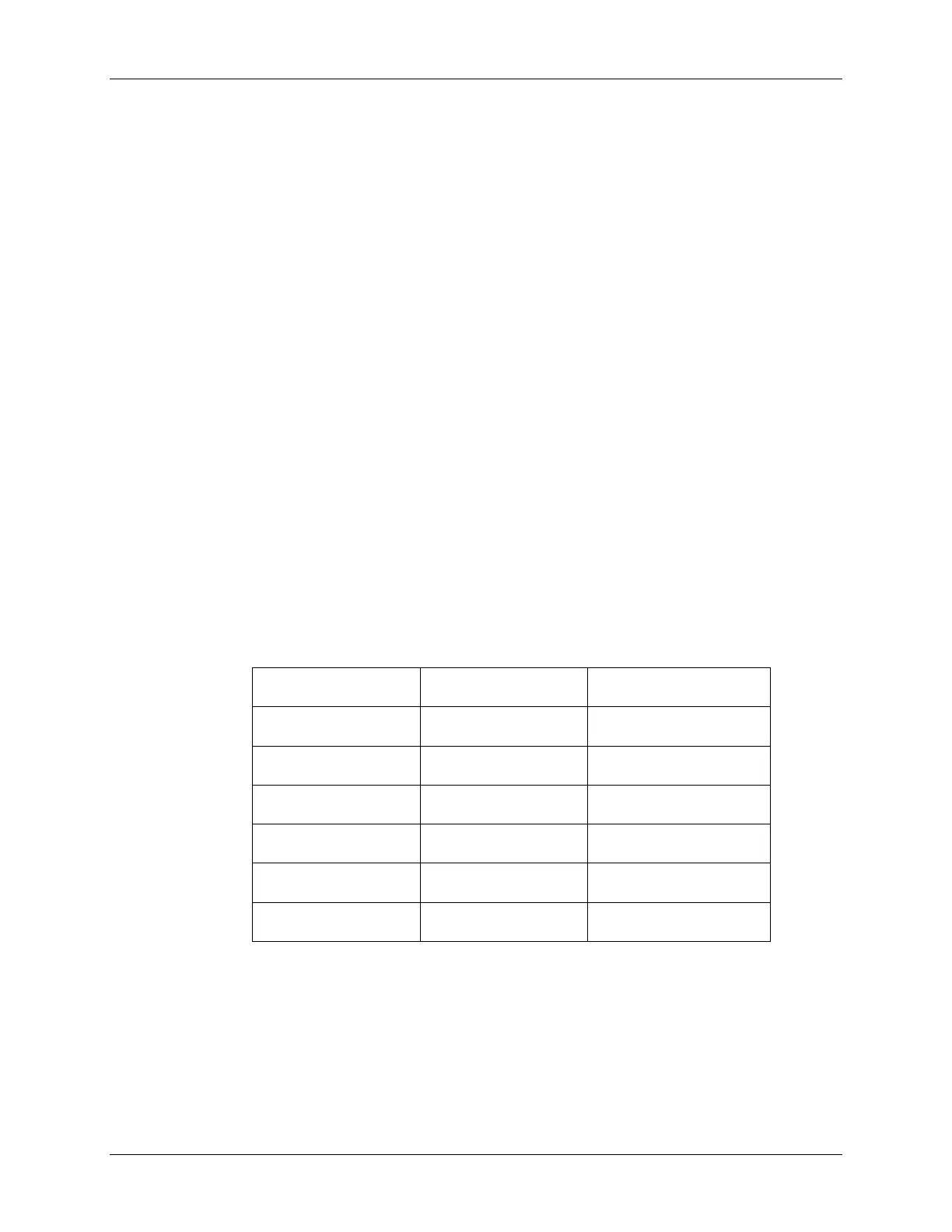
2. This step assigns the RUN address of those sections that need to run from flash. Using
the memory section manager in the DSP/BIOS configuration tool (Lab.cdb) link the
following sections to on-chip flash memory:
DSP/BIOS Data tab DSP/BIOS Code tab Compiler Sections tab
.gblinit .bios .text
.sysinit .switch
.hwi .cinit
.rtdx_text .pinit
.econst / .const
.data
3. This step assigns the LOAD address of those sections that need to load to flash. Again
using the memory section manager in the DSP/BIOS configuration tool (Lab.cdb),
select the Load Address tab and check the “Specify Separate Load
Addresses” box. Then set all entries to the flash memory block.
10 - 20 C28x - System Design
 Loading...


