EasyManuals Logo

Texas Instruments C28 Series Student Guide

Texas Instruments C28 Series
342 pages
To Next Page IconTo Next Page
To Previous Page IconTo Previous Page
Page #29 background imageLoading...
Page #29 background image
Creating a Linker Command File
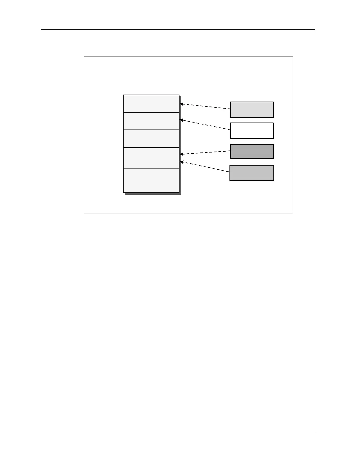
Placing Sections in Memory
.
.
ebss
ebss
.
.
cinit
cinit
.text
.text
Memory
Memory
M0SARAM
M0SARAM
(0x400)
(0x400)
0x00 0000
0x00 0000
0x3D 8000
0x3D 8000
0x00 0400
0x00 0400
M1SARAM
M1SARAM
(0x400)
(0x400)
FLASH
FLASH
(0x20000)
(0x20000)
Sections
Sections
.stack
.stack
Linking code is a three step process:
1. Defining the various regions of memory (on-chip SARAM vs. FLASH vs. External Memory).
2. Describing what sections go into which memory regions
3. Running the linker with “build” or “rebuild”
C28x - Programming Development Environment 2 - 11

Table of Contents

Other manuals for Texas Instruments C28 Series

Questions and Answers:

Question and Answer IconNeed help?

Do you have a question about the Texas Instruments C28 Series and is the answer not in the manual?

Texas Instruments C28 Series Specifications

General IconGeneral
BrandTexas Instruments
ModelC28 Series
CategoryComputer Hardware
LanguageEnglish

Related product manuals