Interrupt Sources
Device Vector Mapping
Device Vector Mapping
-
-
Summary
Summary
_c_int00:
_c_int00:
. . .
. . .
CALL main()
CALL main()
main()
main()
{ initialization();
{ initialization();
. . .
. . .
}
}
Initialization ( )
Initialization ( )
{
{
EALLOW
EALLOW
Load PIE Vectors
Load PIE Vectors
Enable the PIEIER
Enable the PIEIER
Enable PIECTRL
Enable PIECTRL
Enable Core IER
Enable Core IER
Enable INTM
Enable INTM
EDIS
EDIS
}
}
PIE Vector Table
PIE Vector Table
256 Word RAM
256 Word RAM
0x00 0D00
0x00 0D00
–
–
0DFF
0DFF
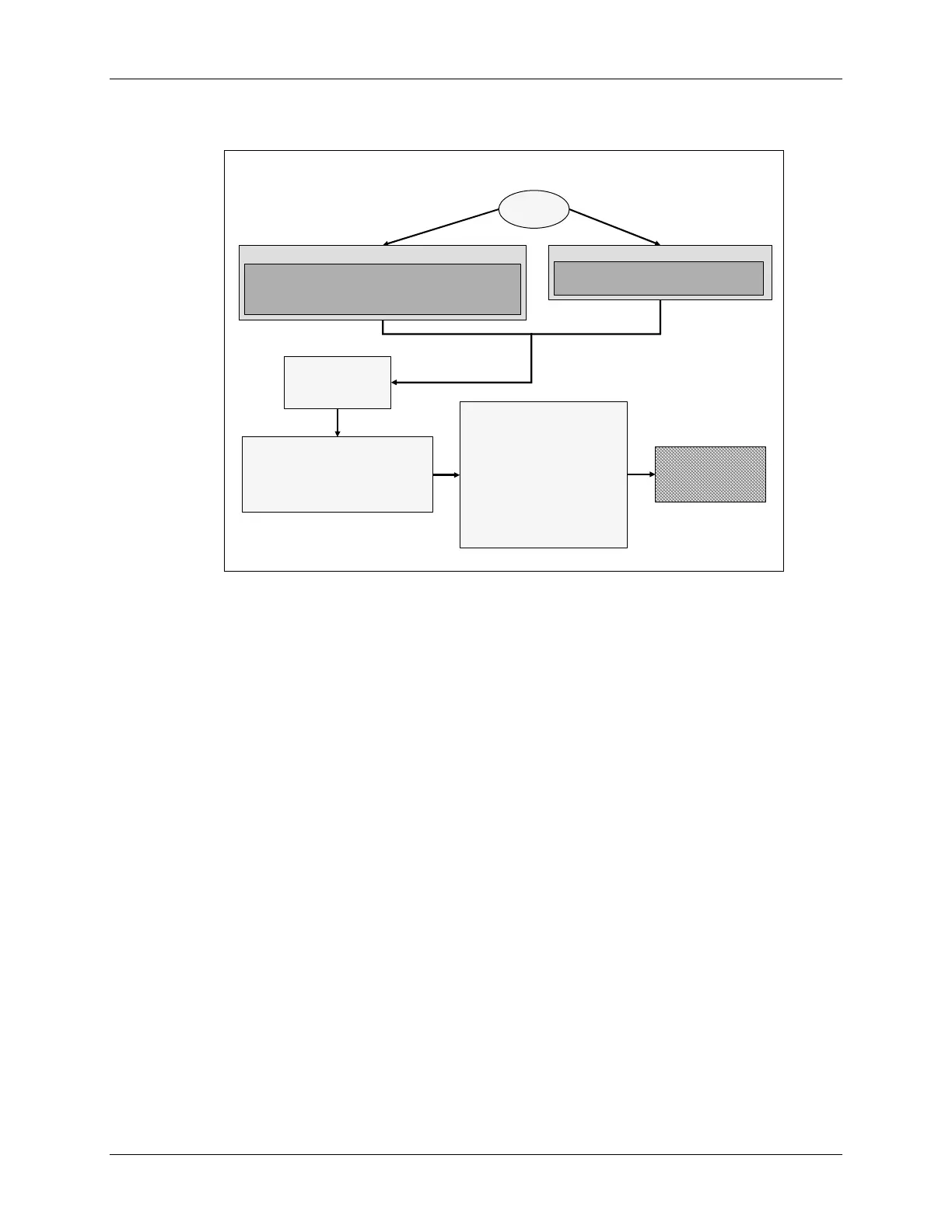
RESET
RESET
Reset Vector <0x3F FFCO> = Boot
Reset Vector <0x3F FFCO> = Boot
-
-
ROM Code
ROM Code
Flash Entry Point <0x3F 7FF6 > = LB _c_int00
Flash Entry Point <0x3F 7FF6 > = LB _c_int00
User Code Start < _c_int00 >
User Code Start < _c_int00 >
MPNMC = 0 (on
MPNMC = 0 (on
-
-
chip ROM memory)
chip ROM memory)
Reset Vector <0x3F FFCO> = _c_int00
Reset Vector <0x3F FFCO> = _c_int00
User Code Start < _c_int00>
User Code Start < _c_int00>
MPNMC = 1 (external memory XINTF)
MPNMC = 1 (external memory XINTF)
4 - 12 C28x - Reset and Interrupts
 Loading...


