Typical Connection and Test Equipment
www.ti.com
12
SNLU223–August 2017
Submit Documentation Feedback
Copyright © 2017, Texas Instruments Incorporated
DS90UB954-Q1EVM Quick Start
5 Typical Connection and Test Equipment
The following is a list of typical test equipment that may be used to monitor the MIPI CSI-2 signals from
the DS90UB954-Q1:
1. Logic Analyzer
2. Any SCOPE with a bandwidth of at least 4 GHz for observing differential signals.
3. UNH-IOL MIPI D-PHY Reference Termination Board (RTB)
4. UNH-IOL MIPI D-PHY/CSI/DSI Probing Board
5. UNH-IOL CSIGUI Tool
6 Termination Device
A termination device is required to properly monitor and measure the transmission of the MIPI DPHY
signals. The termination device should support the change of signals as it switches between LP and HS
modes. This can be provided by either a CSI-2 receiver or a dedicated dynamic termination board. The
recommended termination board is the UNH-IOL MIPI D-PHY Reference Termination Board (RTB).
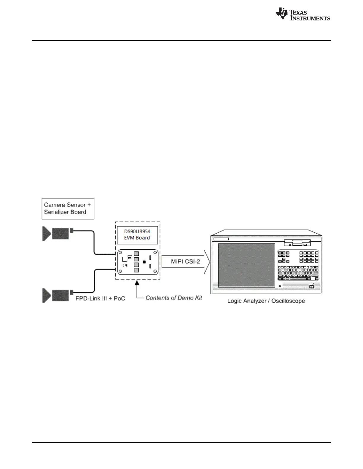
7 Typical Test Setup
Figure 7 illustrate the typical test setups used to measure and evaluate DS90UB954-Q1.
Figure 7 shows a typical test set up using a logic analyzer or oscilloscope.
Figure 7. Typical Test Setup for Evaluation

 Loading...


