www.ti.com
DS90UB954-Q1EVM Board Configuration -Evaluation Board Connections
7
SNLU223–August 2017
Submit Documentation Feedback
Copyright © 2017, Texas Instruments Incorporated
DS90UB954-Q1EVM Quick Start
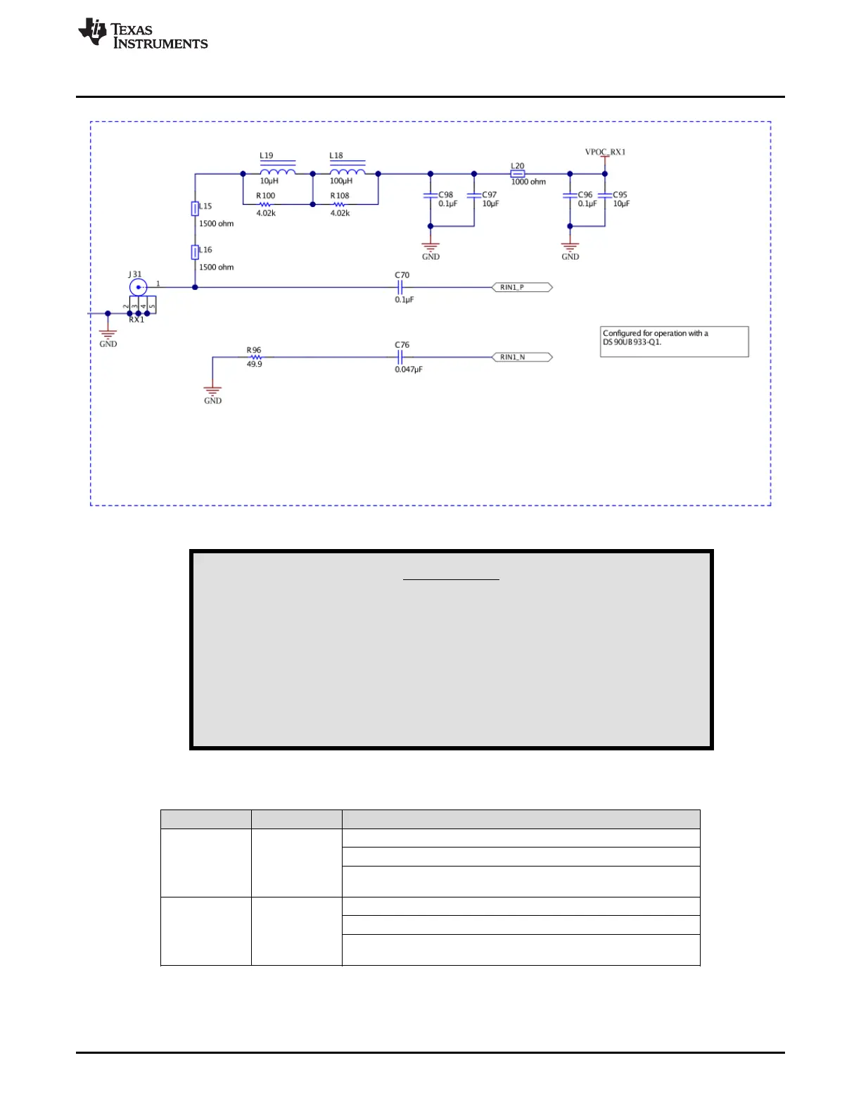
Figure 6. Power Over Coax Network For Use With DS90UB933
WARNING
Verify that the power over coax voltage is properly set before
plugging into RX0 or RX1. Power supply is not fused. Over-voltage
will cause damage to boards directly connected due to incorrect
input power supplies. DS90UB913A-Q1EVM is designed for a
maximum of 5V POC. To use DS90UB913A-Q1EVM with
DS90UB954-Q1EVM, open J17 or J18 to disable POC, and either
power the DS90UB913A-Q1EVM separately or by applying 5V to the
J17 or J18 pin on DS90UB954-Q1EVM.
Table 2. Power Over Coax Power Supply Feed Configuration
Reference Signal Description
J18 VPOC_RX0
This sets the voltage for Power over Coax on RX0
Jumper installed: +9V power supply from VPOC_LDO0_9V
Jumper Open: No POC connected. Apply power to pin1 or leave
open and power serializer separately.
J17 VPOC_RX1
This sets the voltage for Power over Coax on RX1
Jumper installed: +9V power supply from VPOC_LDO1_9V
Jumper Open: No POC connected. Apply power to pin1 or leave
open and power serializer separately.

 Loading...


