DS90UB954-Q1EVM Board Configuration -Evaluation Board Connections
www.ti.com
8
SNLU223–August 2017
Submit Documentation Feedback
Copyright © 2017, Texas Instruments Incorporated
DS90UB954-Q1EVM Quick Start
3.4 MIPI CSI-2 Output Signals
There are two options provided for passing out the deserialized data on the DS90UB954-Q1EVM. The first
is a Samtec QSH-type connector, J24, on the top of the board that can be mated with a matching QTH
type connector. The mating connector part number for the J24 connector is QTH-020-01-H-D-DP-A. On
the bottom of the board is a Samtec QTH-type connector, J26, meant for mating with a TDAx evaluation
kit. The signals to the connectors are the same, including access to I
2
C and other signals including PDB
and GPIO. Only one connector should be used at a time. If the J6 connector on the bottom is to be used,
populate the zero ohm resistors on the bottom of the board which extend the traces to the J26 connector.
There are third party solutions like the HDR-128291-XX breakout board from Samtec which can be used.
The HDR- 128291-XX is a breakout board with a mating connector to J24 or J26, providing access to
each pin through standard SMA male connectors. More info on this breakout board can be obtained from
Samtec website. Another third party option is the ZX100 by Zebax Technologies. More information on this
board can be obtained from Zebax website.
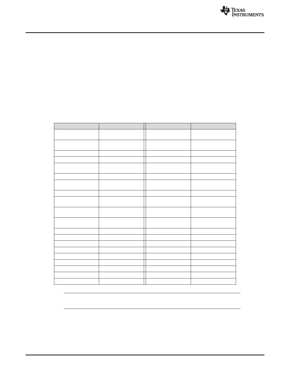
Table 3. MIPI CSI-2 Output Signals - J5 and J6 Pinout
Pin # Signal Name Pin # Signal Name
1 NC 2
EXP_SCL
(I2C_SCL or I2C_SCL2)
3 NC 4
EXP_SDA
(I2C_SDA or I2C_SDA2)
5 CSI_CLK0_P 6 NC
7 CSI_CLK0_N 8 NC
9 CSI_D0_P 10
EXP_REF_CLK
(REFCLK)
11 CSI_D0_N 12 GND
13 CSI_D1_P 14
RESETn
(PDB)
15 CSI_D1_N 16 GND
17 CSI_D2_P 18
SPI_MOSI
(GPIO0 or GPIO3)
19 CSI_D2_N 20
SPI_SCLK
(GPIO1 or GPIO4)
21 CSI_D3_P 22
SPI_CSn
(GPIO2 or GPIO5)
23 CSI_D3_N 24 GND
25 CSI_CLK1_P 26 NC
27 CS_CLK1_N 28 NC
29 NC 30 VDD_3V3
31 NC 32 VDD_3V3
33 NC 34 VDD_3V3
35 NC 36 VDD_3V3
37 NC 38 VDD_1V8
39 NC 40 VDD_1V8
NOTE: Populate R60-R69, R71,R72 (0Ω resistors) only when using the J26 connector on the bottom
of the board. Do not use J24 and J26 connectors at the same time.

 Loading...


