www.ti.com
DS90UB954-Q1EVM Board Configuration -Evaluation Board Connections
9
SNLU223–August 2017
Submit Documentation Feedback
Copyright © 2017, Texas Instruments Incorporated
DS90UB954-Q1EVM Quick Start
3.5 FPD-Link III Signals
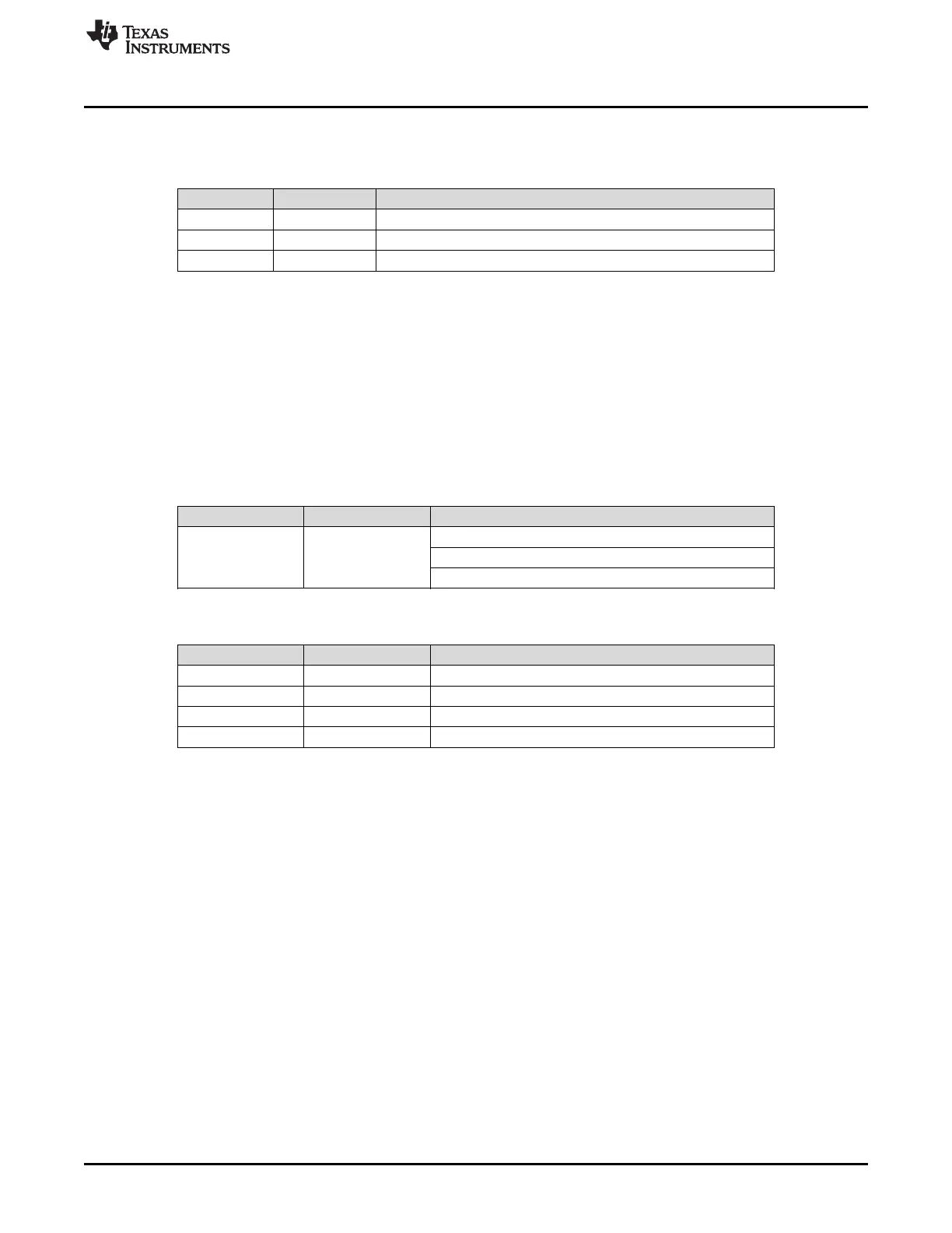
Table 4. FPD-Link III Signals
Reference Signal Description
RX0p RIN0+ FAKRA connector for DS90UB953-Q1 serializer
RX0n RIN0- FAKRA connector footprint for use with STP applications.
RX1 RIN1+ FAKRA connector for DS90UB933-Q1 serializer
3.6 I
2
C Interface
In addition to the on-board USB2ANY controller accessible via the mini-USB port, a standalone external
I
2
C host can connect via J25 for programming purposes. Examples of external I
2
C host controllers are
Texas Instruments USB2ANY and Total Phase Aardvark I
2
C/SPI host adapter (Total Phase Part#:
TP240141).
When the I
2
C interface is accessed through connector J25, I
2
C signal levels can be configured through
J16 to be at 1.8V or 3.3V. Optional access to I
2
C signals are also available via CSI-2 connectors J24 (top)
and J26 (bottom).
Table 5. IDx I
2
C Device Address Select - J23
Reference Signal Description
J23 IDX Select
Selects I
2
C Device Address
Open: 0x30 (7'b) or 0x60 (8'b)
Short: 0x3D (7'b) or 0x7A (8'b) (Default)
Table 6. I
2
C Interface Header - J25
Reference Signal Description
J25.1 VDDIO I
2
C bus voltage (tied to VDDIO)
J25.2 I2C_SCL I
2
C Clock Interface for I
2
C bus
J25.3 I2C_SDA I
2
C Data Interface for I
2
C bus
J25.4 GND Ground
 Loading...


