www.ti.com
Quick Start Guide
5
SNLU223–August 2017
Submit Documentation Feedback
Copyright © 2017, Texas Instruments Incorporated
DS90UB954-Q1EVM Quick Start
2.4 Setup the DS90UB954-Q1EVM
1. Use the mini USB to USB cable to connect J2 to computer USB port for register programming and
open Analog LaunchPAD. See Section 10for details on installing and using Analog LaunchPAD.
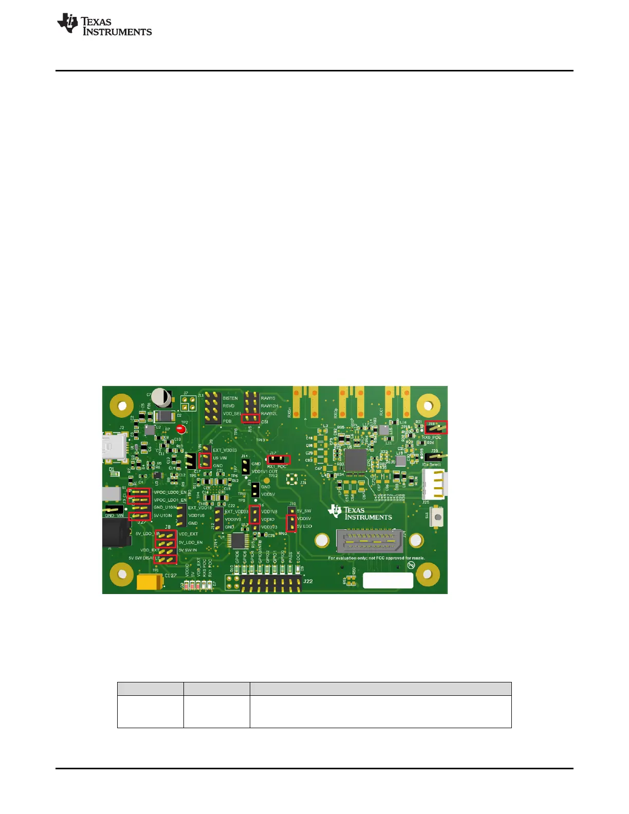
2. Configure jumpers J8, J10, J11, J15, J16, J23, J27, set device’s operating modes. The default
configuration can be see in
3. Configure Power Over Coax power supplies for RX0 and RX1 with J18 and J17 respectively.
4. Connect the DS90UB954-Q1EVM to DS90UB953-Q1EVM to RX0 and/or DS90UB933-Q1EVM to RX1
using coax cable
5. Interface MIPI CSI-2 output signals (J24) to test equipment or host processor (optional, not required to
check status of FPD-Link III connection between serializer and deserializer)
6. Provide power to board. TI recommends using current limited bench supply to provide power to J1
(barrel jack) or J3.
3 DS90UB954-Q1EVM Board Configuration -Evaluation Board Connections
3.1 Default Configuration
Default jumper placement shown in red. This configuration sets the device into the following mode
• Device is set for FPD-Link III inputs from coax in CSI mode (for DS90UB953-Q1)
• VDDIO is set to 1.8V
• VDD5V is powered by the 5V LDO
• The 3.3V + 1.1V LDO (U10) is powered by VDD5V
• The 9V LDO for POC for RX0 and RX1 are enabled
•
Figure 4. DS90UB954-Q1EVM with Jumpers Highlighted
3.2 Power Supply
Table 1. Power Supply
Reference Signal Description
J1/J3 +12V
Main Power
Single +12VDC (nominal) power connector that supplies power to the
entire board.

 Loading...


